Composite wind energy collector

A collector and composite technology, applied in wind power generation, wind turbines, machines/engines, etc., can solve problems such as large volume, and achieve the effect of simplifying structural composition and reducing volume

Active Publication Date: 2016-06-15
凯米特新材料科技有限公司
View PDF5 Cites 14 Cited by
  • Summary
  • Abstract
  • Description
  • Claims
  • Application Information

AI Technical Summary

Problems solved by technology

This type of energy harvester has a high

Method used


Image

  • Composite wind energy collector
  • Composite wind energy collector
  • Composite wind energy collector

Examples


Embodiment 1

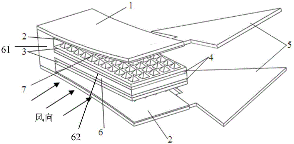
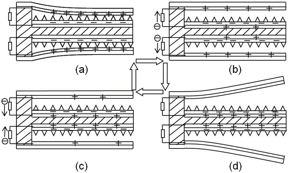
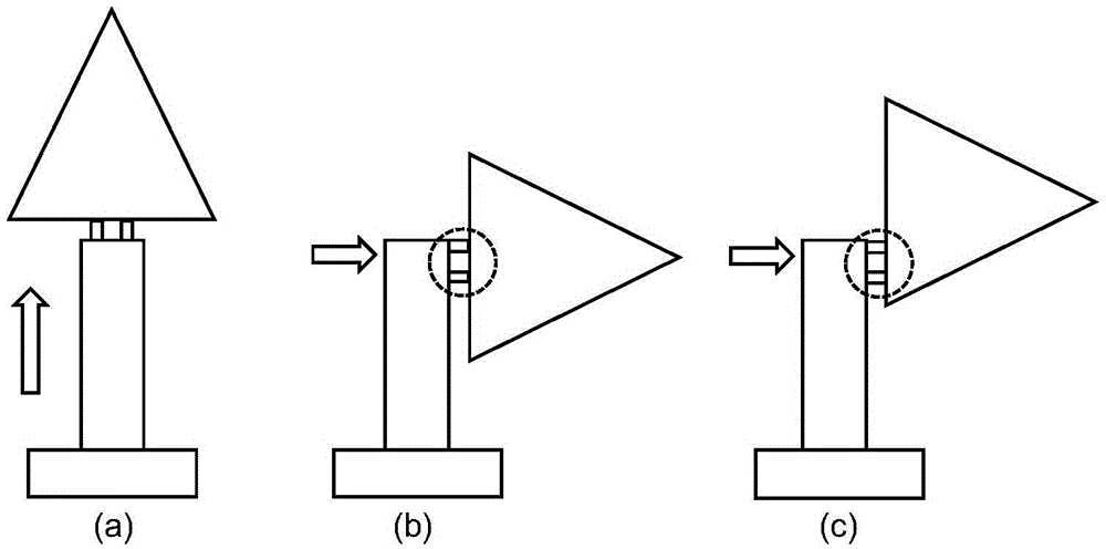
[0035] Such as figure 1 As shown, the composite wind energy collector in the present invention includes a fixed structure frame. In the present embodiment, the fixed structure frame is a T-shaped structure frame 6, and the T-shaped structure frame is placed horizontally. The upper and lower surfaces of the T-shaped structure frame 6 are all sequentially An electrode layer 4 and a polymer layer 3 are provided, and a piezoelectric cantilever 1 is correspondingly provided on the upper and lower sides of the T-shaped structural frame 6. There is a swing space between the piezoelectric cantilever beam 1 and the surface of the T-shaped structural frame 6, and the piezoelectric cantilever A metal friction layer 2 is provided on the surface of the beam 1 opposite to the T-shaped structural frame 6 to form two groups of composite wind energy collectors arranged symmetrically up and down. Wherein, the T-shaped structural frame can also be placed vertically, and the specific method is no...

Embodiment 2

[0045] The rest are the same as in Embodiment 1, the difference is that the fixed structure frame can be an L-shaped structure, the electrode layer and the polymer layer on it are all arranged on the upper surface of the L-shaped structure frame, and the fixed end of the piezoelectric cantilever beam is fixed On the top of the L-shaped structural frame, the metal friction layer is located on the inner surface of the piezoelectric cantilever beam, forming a group of composite wind energy collectors. Among them, multiple sets of composite wind energy collectors can also be set, and the specific implementation method can be set according to needs, and there is no limitation here.

[0046] In addition, the positions of the metal friction layer, the high molecular polymer layer and the electrode layer can also be interchanged, the metal friction layer is arranged on the fixed structure frame, and the electrode layer and the high molecular polymer layer are arranged on the inner surf...


PUM


Abstract

The invention discloses a composite wind energy collector. An electrode layer and a high-molecular polymer layer are arranged on both the upper surface and the lower surface of a T-shaped structural frame, the upper side and the lower side of the T-shaped structural frame are respectively provided with a piezoelectric cantilever beam, and the surface on the side, opposite to the T-shaped structural frame, of each piezoelectric cantilever beam is provided with a metal friction layer, so that two groups of composite wind energy collectors arranged in longitudinal symmetry are formed. The wind energy collectors combine piezoelectric wind energy collection modules and friction type wind energy collection modules. In work, wind blows to the wind energy collectors from the side surface, the wind power enables blades to swing and further drive the piezoelectric cantilever beams to swing up and down periodically, positive and negative charges in the piezoelectric cantilever beams are separated, and alternating currents are generated and output; and meanwhile, the metal friction layers and the high-molecular polymer layers are separated periodically, electron flowing is realized, and alternating current output is formed. According to the invention, the piezoelectric and friction wind energy collection modes are effectively combined, and the high power output of the wind energy collectors under a low wind speed is realized.

Description

technical field [0001] The invention belongs to the technical field of structural design of wind energy collectors, in particular to a composite wind energy collector. Background technique [0002] Wind energy is a renewable and clean energy that exists widely in nature. Harvesting wind energy to power wireless sensor networks and embedded low-power electronic devices that work outdoors has broad prospects. [0003] At present, there are three main ways to convert wind energy into electrical energy: electromagnetic, piezoelectric and friction. The electromagnetic type is a traditional way of collecting wind energy. Usually, the structure of the windmill is used to drive the rotor and the stator to move relative to each other, so as to cut the magnetic induction lines to generate induced electromotive force. This kind of wind energy collector has a large volume, complex structure and high manufacturing cost. Piezoelectric wind energy collectors are usually designed as a can...

Claims


Application Information

Patent Timeline
IPC IPC(8): H02N2/18F03D5/06H02N1/04
CPCY02E10/70H02N2/183F03D5/06H02N1/04
Inventor 刘会聪陈涛夏月冬孙立宁刘文杰
Owner 凯米特新材料科技有限公司
Why Eureka
Try Eureka