Drill bit special for carbon fiber composite

A composite material and carbon fiber technology, which is applied in the direction of drill repair, twist drill, drilling tool accessories, etc., can solve the problems of fiber scattering, burning attachments and burrs, easy delamination, etc., to avoid delamination, efficient chip breaking and Chip removal function, the effect of improving the pass rate

Inactive Publication Date: 2016-06-22
HARBIN UNIV OF SCI & TECH
View PDF6 Cites 4 Cited by
  • Summary
  • Abstract
  • Description
  • Claims
  • Application Information

AI Technical Summary

Problems solved by technology

[0004] The purpose of the present invention is to provide a special drill bit for carbon fiber composite materials to solve the problems of easy delamination of carbon fiber composite materials, scattering of fibers, generation of burning deposits and burrs during the drilling process of carbon fiber composite materials, thereby improving the efficiency of the carbon fiber processing process and the quality of workmanship of the parts

Method used


Image

  • Drill bit special for carbon fiber composite
  • Drill bit special for carbon fiber composite
  • Drill bit special for carbon fiber composite

Examples


specific Embodiment approach 1

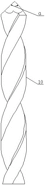
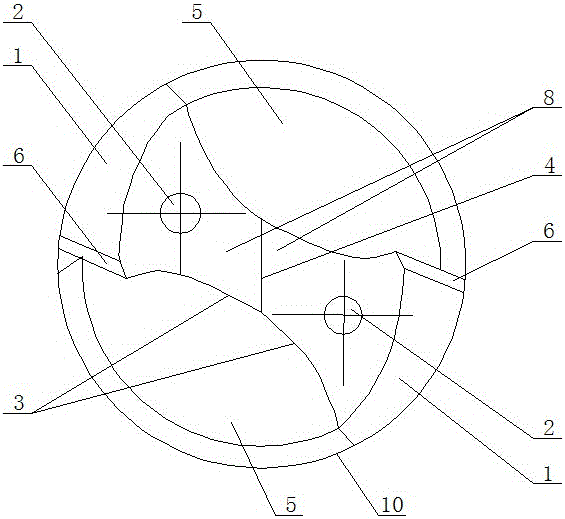
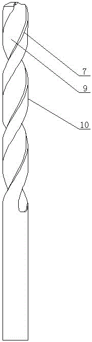
[0018] Specific implementation one: as Figure 1~Figure 4 As shown, this embodiment discloses a special drill bit for carbon fiber composite materials, including a drill bit main body 10, and the outer circumferential surface of the drill bit main body 10 is axially machined with two spiral grooves 5. The two spiral grooves 5. The direction of rotation is the same, and the flank 1 arranged on the conical surface of the head of the drill main body 10 is divided into two by two flat grooves 8, and the axial cross-sections of the two flat grooves 8 are arc-shaped, The junction of the two flat grooves 8 is a raised chisel edge 4, the chisel edge 4 is arranged at the center of the head of the drill main body 10, and the two flat grooves 8 are symmetrically arranged with respect to the chisel edge 4; The rake face 9 and the flank face 1 at the helical groove 5 of the drill main body 10 are connected by a chamfer (that is, the rake face 9 and the flank face 1 are separated by the cha...

specific Embodiment approach 2

[0023] Specific implementation two: as figure 1 and figure 2 As shown, in the special drill bit for carbon fiber composite materials according to the first embodiment, the included angle between the two flank surfaces 1 located on the generatrix of the same axial section is α, and α=90°.

[0024] The included angle α=90° between the two said flank faces 1 located in the same axial section of the generatrix, which is different from the 140° drill tip angle used by general solid carbide drills, can effectively avoid the occurrence of drilling. Delamination and burr phenomena.

specific Embodiment approach 3

[0025] Specific implementation three: as Figure 1~Figure 4 As shown, in the special drill bit for carbon fiber composite material according to the first embodiment, the secondary cutting edge 7 arranged on the outer edge of the side wall of the spiral groove 5 of the drill bit main body 10 forms an included angle of 45° with the flank 1 . Here are common structural parameters designed for the manufacturing process.


PUM

PropertyMeasurementUnit
diameteraaaaaaaaaa

Abstract

The invention discloses a drill bit special for a carbon fiber composite, relates to the technical field of drilling tools, and aims to solve the problems that the carbon fiber composite is high in possibility of delamination, fiber dispersion, and burning attachment and burr generation in the drilling machining process. The drill bit special for the carbon fiber composite comprises a drill body, wherein two spiral grooves are processed in the outer circumference surface of the drill body in the axial direction, and are consistent in the turning direction; a flank surface arranged on the conical surface at the head part of the drill body is divided into two parts through two flat grooves; the axial cross sections of the two flat grooves are both arc-shaped; a raised chisel edge is arranged at the joint of the two flat grooves, and is arranged in the center of the head part of the drill body; the two flat grooves are symmetrically arranged relative to the chisel edge; a rake surface and the flank surface are connected through an inclined plane; the inclined plane is a second cutting edge. The phenomena of delamination, burrs and burns in the drilling process of the carbon fiber composite can be effectively avoided, the drilling defects can be reduced, and the processing efficiency and the processing quality can be improved, so that the qualified rate of the product can be improved.

Description

technical field [0001] The invention relates to the technical field of drilling tools, in particular to a special drill bit for carbon fiber composite materials. Background technique [0002] Carbon fiber composite material is an important development direction in the field of materials. Most of its processing methods are drilling, but the principle is different from that of metal. When machining carbon fiber composites, sharp edges are used to forcibly break the fibers and cut the epoxy layer, which in turn rubs and wears the tool. When processing composites, it should not cause delamination, fiber unraveling, burning deposits, and burrs. However, due to the structural problems of ordinary drill bits, it is difficult to avoid the above problems when drilling carbon fiber composite materials. [0003] The main problems when drilling carbon fiber composite materials are: the material resistance changes when drilling each layer and the sudden disappearance of the force when ...

Claims


Application Information

Patent Timeline
Patent Type & Authority Applications(China)
IPC IPC(8): B23B51/02B23B51/06
CPCB23B51/02B23B51/06
Inventor 陈涛王艳艳刘献礼杨辰
Owner HARBIN UNIV OF SCI & TECH
Why Eureka
Try Eureka