Processing tools and inserts for processing tools

A technology for machining tools and inserts, applied in the field of inserts, can solve the problem of not finding the specification of insert size, and achieve the effect of improving surface quality, small cutting power, less friction and heat

Active Publication Date: 2021-07-27
OERTLI WERKZEUGE
View PDF6 Cites 0 Cited by
  • Summary
  • Abstract
  • Description
  • Claims
  • Application Information

AI Technical Summary

Problems solved by technology

In the document EP-A-1442852 no instructions for dimensioning the blades are found

Method used


Image

  • Processing tools and inserts for processing tools
  • Processing tools and inserts for processing tools
  • Processing tools and inserts for processing tools

Examples


Embodiment Construction

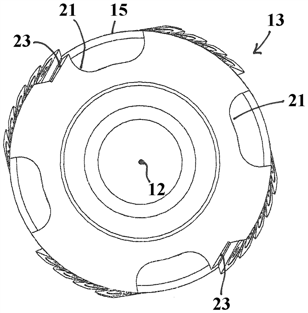
[0057] figure 1 and 2 In a perspective view, an embodiment of the invention for the treatment of materials (in particular for wood or wood-based materials such as coated or uncoated Spanplatte, hardboard or the like) A first embodiment of a machining tool 11 for cutting. However, the processing tool 11 can also be suitable for other materials such as fiber composite plastic or the like. The machining tool 11 is designed as a helical milling cutter and is provided for mounting on a tool shank (not shown). Drive processing tool 11 to rotate around axis of rotation 12 in operation ( figure 1 ).

[0058] The base body 13 of the machining tool 11 is substantially cylindrical, wherein on its cylindrical peripheral surface 15 a plurality of inserts 17 in the form of peripheral knives with cutting edges 19 are arranged. The blades 17 are arranged in at least one row, preferably at least two or more rows arranged in the peripheral direction, wherein the rows or groups overlap each...


PUM


Abstract

The invention relates to a machining tool and a blade for a machining tool, in particular a machining tool for rotary cutting machining of a material (42), especially for wood or wood-based, plastic and / or composite materials (11b) comprising at least one row of substantially square blades (17) in top view with curved blades (19) arranged in the peripheral direction, having a wedge angle β and rotating at an axis angle λ relative to Axis (12) is arranged. The cutting edge (19) of the square blade (17) has a length greater than 13mm and less than 15mm, an edge radius less than 50mm and a wedge angle β less than 60° and greater than 45°.

Description

technical field [0001] The invention relates to a machining tool (Bearbeitungswerkzeug) especially for wood or wood-based materials, plastics and / or composite materials, as well as a blade (Schneidplatte) for the machining tool. Background technique [0002] When machining materials, especially wood, a flat (glatt) surface that does not need to be reworked is usually aimed for. In order to achieve this, the tool geometry of the machining tool must be optimized. Precisely when processing wood or wood-based materials, however, various adverse effects can be observed which impair the quality of the processed surface. So-called pre-splitting can occur, for example, when cutting wood when a crack called a pre-splitting in the fiber direction precedes the cutting tool during chip removal. Although this pre-cracking facilitates machining and prolongs the service life of the tool, it also leads to an undesirably rough surface. Furthermore, if the wood surface is treated with, for...

Claims


Application Information

Patent Timeline
Patent Type & Authority Patents(China)
IPC IPC(8): B23C5/04B23C5/20B27G13/00B27G13/04
CPCB23C5/04B27G13/005B27G13/04B23C5/202B23C2200/0461B23C2200/203B23C2210/04B23C2210/0407B23C2210/0485
Inventor B.埃尔勒
Owner OERTLI WERKZEUGE
Why Eureka
Try Eureka