A kind of multipurpose hydraulic vise and working method thereof

A flat-nose pliers, hydraulic technology, applied in the direction of manufacturing tools, metal processing equipment, metal processing machinery parts, etc., can solve the problems of inability to process safety accidents, high parallelism requirements, unstable clamping workpieces, etc., to achieve operation and maintenance Low cost, simple and compact structure, easy to popularize and use

Active Publication Date: 2018-01-09
湖南益谋智能科技有限公司
View PDF7 Cites 0 Cited by
  • Summary
  • Abstract
  • Description
  • Claims
  • Application Information

AI Technical Summary

Problems solved by technology

In mechanical processing, when drilling, milling, and processing parts in machining centers, flat-nose pliers are often used to clamp workpieces, but ordinary flat-nose pliers have high requirements for the parallelism of the clamped workpieces, and often can only clamp and fix relatively regular workpieces , but when the two surfaces of the workpiece are not parallel (that is, the often-called special-shaped parts), the clamping of the workpiece is not stable, which affects the machining accuracy, and even cannot be processed or cause safety accidents
[0003] The Chinese patent, the application number is: CN204053832U, discloses a hydraulic vise; the patent injects hydraulic oil into the hollow rubber sleeve to expand the rubber sleeve to clamp the pipe, and adjusts the stroke of the hydraulic cylinder to drive the slider to clamp the ordinary parts. The clamping is mainly achieved by the expansion of the rubber sleeve, resulting in a small clamping force, and can only clamp objects with smooth surfaces, and the application range is small
[0004] The Chinese patent, the application number is: CN203566522U, discloses a special hydraulic vise for the production of transmission towers; this patent is a special hydraulic vise for the production of transmission towers, the vise is fixed on the bracket connected, cannot move, and the structure is relatively complicated Not suitable for machine tool processing

Method used


Image

  • A kind of multipurpose hydraulic vise and working method thereof
  • A kind of multipurpose hydraulic vise and working method thereof
  • A kind of multipurpose hydraulic vise and working method thereof

Examples


Embodiment

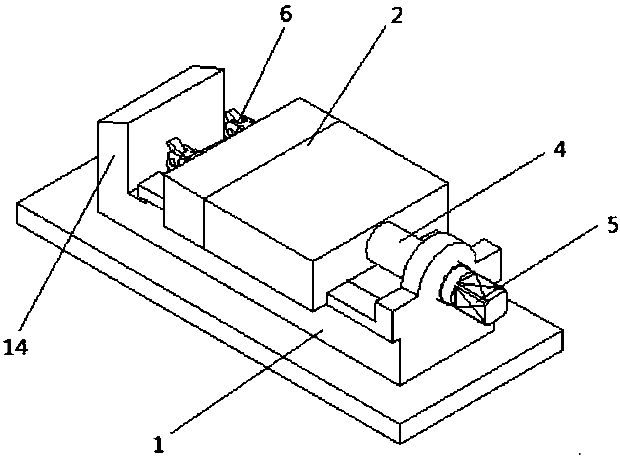
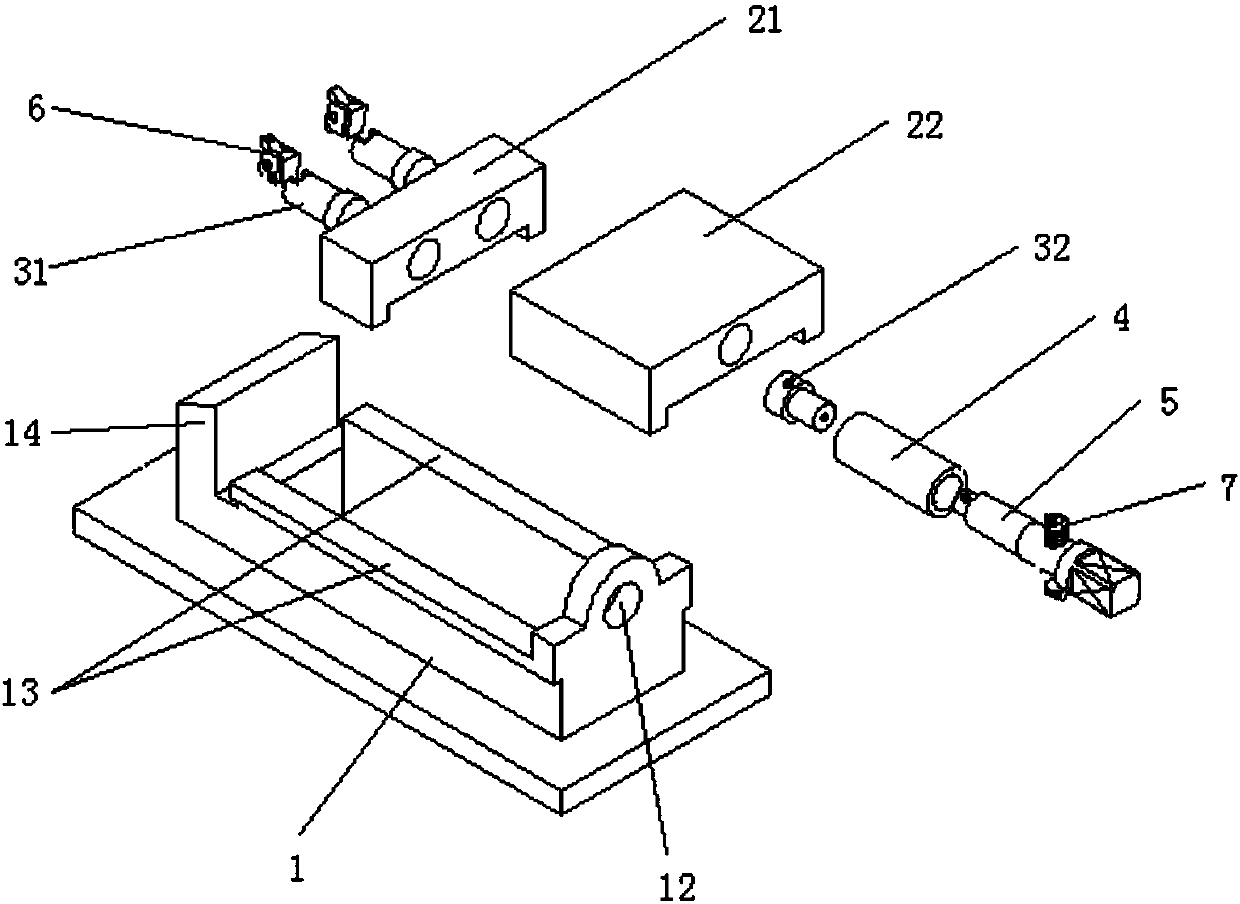
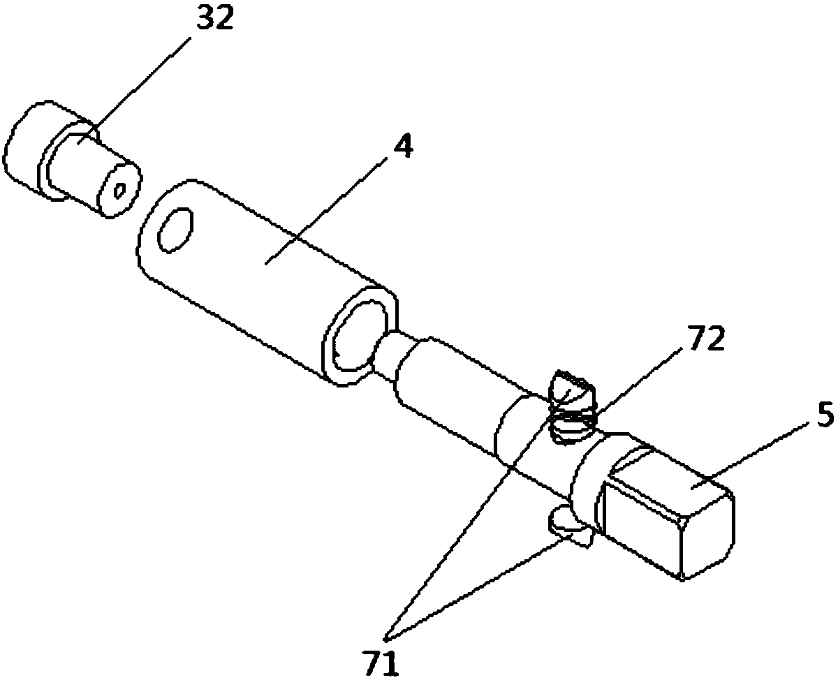
[0028] A kind of multipurpose hydraulic vise of the present invention, as Figure 1 to Figure 5 As shown, it includes a fixed clamp body 1, a movable clamp body assembly 2, a central plunger pump assembly 3, and a pre-clamping screw 4; the shown fixed clamp body 1 is provided with two rows of parallel guide rails 13; One end of one end is provided with a connecting ear plate, and the ear plate is provided with screw hole 12, and the other end is provided with the baffle plate 14 of vertical base, and wherein between two rows of guide rails is a leaky structure; Move on the fixed clamp body 1; wherein the movable clamp body assembly 2 includes a movable clamp body 21 and a movable clamp body main body 22 fixedly connected together; the central plunger pump assembly 3 is located inside the movable clamp body assembly 2; the central column The plug pump assembly 3 includes: two clamp piston rods 31 installed symmetrically on the left and right sides and a central plunger pump plu...


PUM


Abstract

The invention discloses multipurpose hydraulic flat tongs. The multipurpose hydraulic flat tongs comprise a fixed tong body, a movable tong body assembly, a central plunger pump assembly, a pre-clamping screw and a clamping screw. The pre-clamping screw and the clamping screw push the movable tong body assembly to move on the fixed tong body through rotation of the pre-clamping screw and the clamping screw, and a workpiece is clamped through the central plunger pump assembly. According to a working method of the multipurpose hydraulic flat tongs, the movable tong body moves forwards by rotating the pre-clamping screw; and after force is increased, pawl pins press down a spring, the clamping screw continues rotating, a central plunger pump plunger is pushed to generate high pressure oil, therefore two workpiece clamping piston rods are pushed to move, and the workpiece is clamped. Meanwhile, the multipurpose hydraulic flat tongs and the working method thereof also have the advantages that the design is reasonable, and the structure is simple and compact; the service life is long; the application range is wide; the production, operation and maintaining cost is low; and the multipurpose hydraulic flat tongs are convenient to apply and popularize.

Description

technical field [0001] The invention relates to the technical field of mechanical processing, in particular to a multi-purpose hydraulic vise and a working method thereof. Background technique [0002] Flat-nose pliers, also known as machine vises, are a general-purpose fixture that is often used to install small workpieces. It is a random accessory for milling machines and drilling machines. It is fixed on the machine tool table and used to clamp the workpiece for cutting. In mechanical processing, when drilling, milling, and processing parts in machining centers, flat-nose pliers are often used to clamp workpieces, but ordinary flat-nose pliers have high requirements for the parallelism of the clamped workpieces, and often can only clamp and fix relatively regular workpieces , but when the two surfaces of the workpiece are not parallel (that is, the so-called special-shaped parts), the clamping of the workpiece is not stable, which affects the machining accuracy, and even ...

Claims


Application Information

Patent Timeline
Patent Type & Authority Patents(China)
IPC IPC(8): B23Q3/08
CPCB23Q3/082
Inventor 王稳郑勇刘红月
Owner 湖南益谋智能科技有限公司
Why Eureka
Try Eureka