Laser black marking method of automatic production line

An automatic production line, black technology, applied in the field of laser black marking, can solve the problems of low contrast, large ink consumption, difficult to identify, etc., to achieve high recognition rate, improve quality, and enhance the effect of absorption

Active Publication Date: 2016-06-22
GUANGDONG UNIV OF TECH
View PDF16 Cites 2 Cited by
  • Summary
  • Abstract
  • Description
  • Claims
  • Application Information

AI Technical Summary

Problems solved by technology

[0003] Laser marking technology can be used for marking transparent materials. In traditional transparent material marking, there are currently three main methods: ① Using CO 2 Laser is used for direct marking, but the contrast of this method is not high, and it is difficult to identify on light-colored materials; ② Green laser is used for direct marking, but the cost of green laser equipment is relatively high
③Using inkjet + infrared laser marking, this method consumes a lot of ink, the cost of ink consumables is also high, and has certain pollution to the environment, and the marks marked by this method are not corrosion-resistant or water-resistant
However, during the marking process, the sample needs to be precisely positioned. In addition, each marking takes a certain amount of time. During this time, the position of the vibrating lens and the sample must be kept relatively fixed to ensure that the laser The marked mark is positioned accurately and does not deform, otherwise it will affect the quality of the mark and cause the marked barcode to not be recognized quickly and accurately
Because the graphite back engraving method is used, due to the high temperature of the laser beam, the glass sample may adhere to the graphite sheet, thereby affecting the delivery of the glass sample; in addition, after the glass sample is marked, the surface of the sample may be damaged. Graphite dust will be attached, which is not conducive to the identification of marked barcodes

Method used


Image

  • Laser black marking method of automatic production line
  • Laser black marking method of automatic production line
  • Laser black marking method of automatic production line

Examples


Embodiment

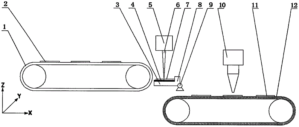
[0020] The laser black marking method of a kind of automatic production line of the present invention comprises the following steps:

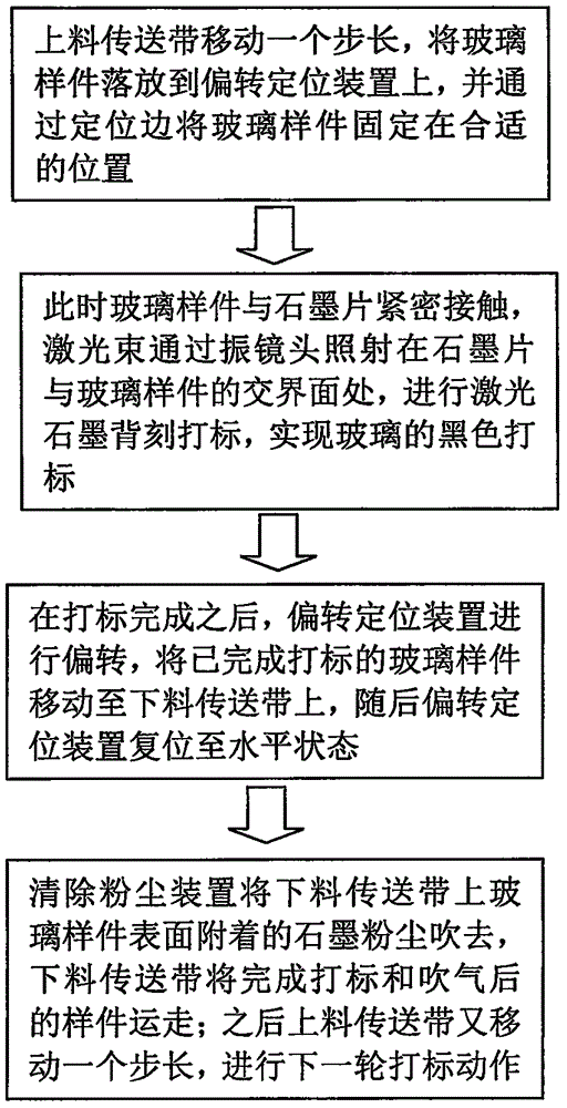
[0021] 1) The feeding conveyor belt 1 transports the glass sample 2 to be processed;

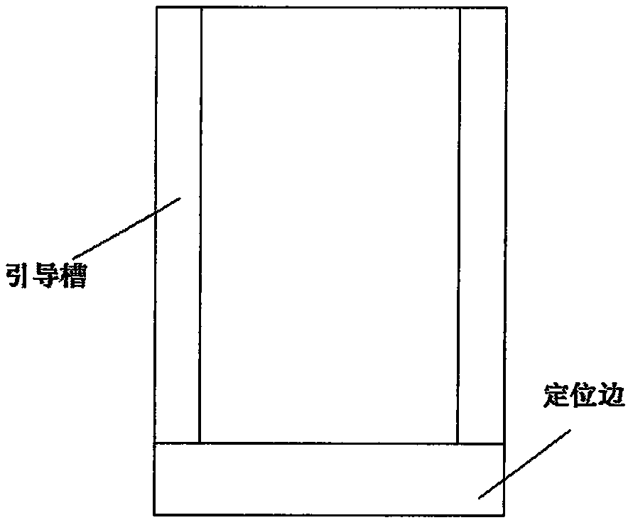
[0022] 2) deflect the glass sample 2 to be processed above the positioning device 3, and accurately position the glass sample 2 to be processed by the positioning edge 8, so that the glass sample 2 to be processed is in close contact with the graphite sheet 4;

[0023] 3) irradiating the laser beam 6 on the contact surface between the glass sample 2 to be processed and the graphite sheet 4;

[0024] 4) Under the action of the laser beam 6, the graphite sheet 4 is violently ablated, and an instantaneous high temperature and high pressure is formed between the graphite sheet 4 and the glass sample 7 being processed, and the graphite sheet 4 is violently ablated on the glass sample being processed. A deposition layer is formed on the glass sample 7, and the dep...


PUM


Abstract

The invention discloses a laser black marking method of an automatic production line. The method includes the following steps: 1) a feeding conveyor belt moves by one step length to move a sample piece onto a deflection device, and the sample piece is fixed in an appropriate position through a locating edge; 2) the sample piece is in close contact with a graphite flake, a laser beam is focused on an interface of the graphite flake and the sample piece, back etching marking is performed, and a black mark is realized; and 3) after marking is completed, the deflection device deflects to move the sample piece to a discharging conveyor belt, soon afterwards a deflection positioning device is reset to a horizontal state, a dust clearing device blows graphite dust away, and the discharging conveyor belt carries the sample piece away; and then the feeding conveyor belt moves by one step length again, and a next round of marking is performed. The marking method provided by the invention is stable in structure, accurate in positioning, convenient to operate, high in production efficiency, low in operation labor intensity, easy to operate, and low in cost of materials consumed by marking, and can realize high-quality black marking of glass on a laser automatic production line.

Description

technical field [0001] The invention relates to a laser black marking method of an automatic production line, in particular to the design of the glass black laser marking method on the automatic production line. Background technique [0002] Marking is a technique widely used in the production process. Laser marking is the process of scanning the target surface with a laser beam of appropriate energy density and converging on the surface of the workpiece, causing physical or chemical changes in the material, forming marks on the surface, and forming a mark. It belongs to a non-contact marking method. Compared with traditional processing methods, it has the advantages of wide application range, fast marking speed, stable performance, high quality, low operating cost, little environmental pollution, easy computer control and synchronous operation with other equipment. Therefore, laser marking has become one of the important application fields of laser. [0003] Laser markin...

Claims


Application Information

Patent Timeline
IPC IPC(8): B41J2/435B41J3/407B41J29/17
CPCB41J2/435B41J3/407B41J29/17
Inventor 谢小柱江伟魏昕胡伟翁清
Owner GUANGDONG UNIV OF TECH
Why Eureka
Try Eureka