
Body Positioning Device of On-load Capacitance Adjusting Amorphous Alloy Transformer

An amorphous alloy, positioning device technology, applied in the direction of transformer/reactor installation/support/suspension, transformer/inductor parts, transformers, etc., can solve the problems of transformer parts damage, affecting transformer accuracy, transformer function failure, etc. Achieve the effect of ensuring accurate positioning, improving positioning accuracy and increasing contact area

Active Publication Date: 2017-12-01
NANNING NANTE TRANSFORMER MFG
View PDF8 Cites 0 Cited by
  • Summary
  • Abstract
  • Description
  • Claims
  • Application Information

AI Technical Summary

Problems solved by technology

[0003] The positioning of the on-load capacity-adjusting amorphous alloy transformer body is very important for oil-immersed transformers. Once the positioning is not good enough, the transformer body will shift during transportation and handling, or collide with the oil tank, resulting in damage to the transformer parts or the oil tank. damage, and then make the transformer function invalid
The positioning accuracy of some existing positioning devices is not enough, the stability of the body in the oil tank is not enough, and the body is easy to shake. Larger, in severe cases, it will affect the accuracy of the transformer

Method used


Image

  • Body Positioning Device of On-load Capacitance Adjusting Amorphous Alloy Transformer
  • Body Positioning Device of On-load Capacitance Adjusting Amorphous Alloy Transformer
  • Body Positioning Device of On-load Capacitance Adjusting Amorphous Alloy Transformer

Examples


Embodiment Construction

[0028] The present invention will be further described in detail below in conjunction with the accompanying drawings, so that those skilled in the art can implement it with reference to the description.

[0029] It should be understood that terms such as "having", "comprising" and "including" as used herein do not entail the presence or addition of one or more other elements or combinations thereof.

[0030] It should be noted that the experimental methods described in the following embodiments, unless otherwise specified, are conventional methods, and the reagents and materials, if not otherwise specified, can be obtained from commercial sources; in the description of the present invention, The terms "landscape", "portrait", "top", "bottom", "front", "rear", "left", "right", "vertical", "horizontal", "top", "bottom", The orientation or positional relationship indicated by "inner", "outer", etc. is based on the orientation or positional relationship shown in the drawings, whic...


PUM

PropertyMeasurementUnit
Radiusaaaaaaaaaa

Abstract

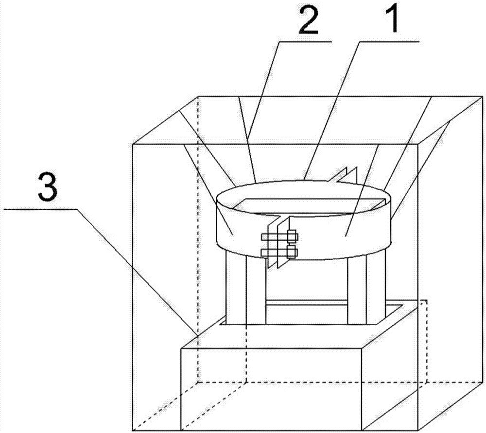
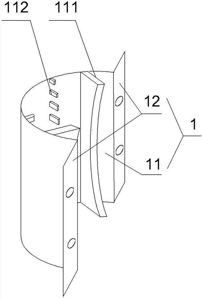
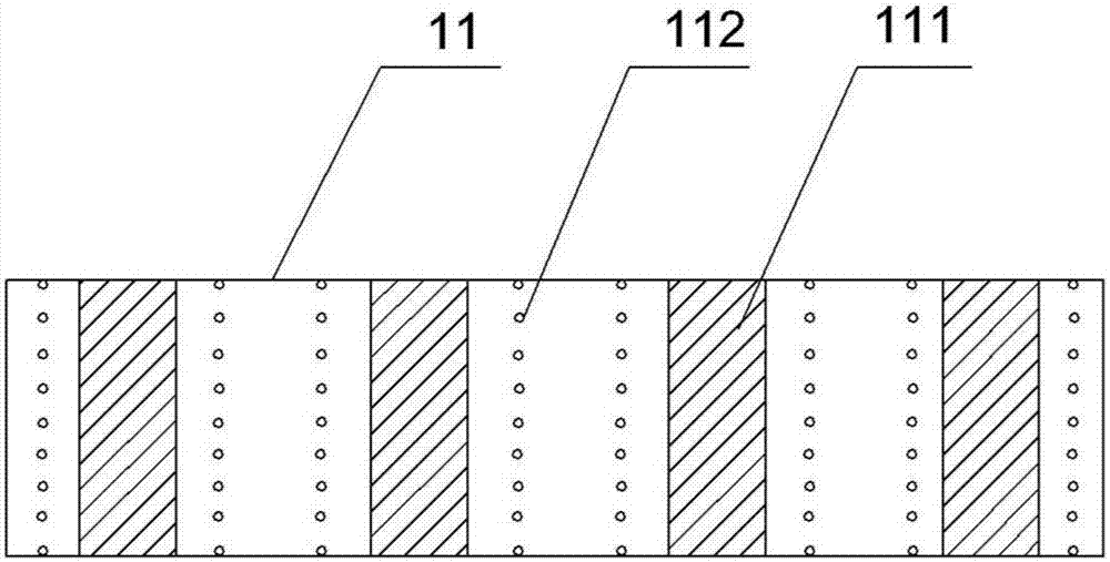
The invention discloses a transformer body positioning apparatus for an on-load capacity-adjusting type amorphous alloy transformer. The transformer body positioning apparatus is used for fixing the transformer body of the on-load capacitor-tuning type amorphous alloy transformer in an oil tank; the transformer body positioning apparatus comprises a pair of hoop bodies, multiple metal rods and a positioning base, wherein the pair of hoop bodies are detachably connected through a connecting piece, and tightly clamps the upper part iron yoke on the transformer body; multiple first convex ridges and multiple first convex part groups are uniformly distributed on the inner walls of the loop bodies; the positioning base is fixed at the bottom of the oil tank; a positioning groove is formed in the positioning base, and the lower part iron yoke of the transformer body is just accommodated in the positioning groove; multiple second convex ridges and multiple second convex part groups are uniformly distributed on the inner wall of the positioning groove, wherein the vertical outlines of the first convex ridges are hyperbolic curves while the vertical outlines of the second convex ridges are parabolic curves. Due to the upper part loop bodies and the lower part positioning base, the positioning accuracy of the transformer body can be improved and the stability of the transformer body in the oil tank can be reinforced; and in addition, the transformer body positioning apparatus has excellent anti-vibration and vibration-damping performances.

Description

technical field [0001] The invention relates to an amorphous alloy on-load capacity regulating transformer. More specifically, the present invention relates to a body positioning device of an on-load capacity regulating amorphous alloy transformer Background technique [0002] The on-load capacity regulating amorphous alloy transformer is the main power distribution equipment of the power system distribution network. A transformer is a device that uses the principle of electromagnetic induction to change the AC voltage. It mainly includes a primary coil, a secondary coil and an iron core, which can realize voltage conversion, current conversion, impedance conversion, isolation, and voltage stabilization (magnetic saturation transformer). High-power transformers are commonly used in the field of long-distance power transmission. Usually, after the power plant generates electricity, a step-up transformer (multi-stage step-up) is used to increase the voltage of the electric e...

Claims


Application Information

Patent Timeline
IPC IPC(8): H01F29/04H01F27/06H01F27/00
CPCH01F27/00H01F27/06H01F29/04
Inventor 覃再兴黎斌唐仕平
Owner NANNING NANTE TRANSFORMER MFG
Learn More