
Converter valve voltage-sharing state consistency statistics method

A statistical method, converter valve technology, applied in the direction of converting AC power input to DC power output, information technology support systems, output power conversion devices, etc. Monitor the presence or absence of status feedback signals and other issues to achieve the effect of improving safe and reliable operation capabilities

Active Publication Date: 2016-06-22
NR ELECTRIC CO LTD +1
View PDF5 Cites 8 Cited by
  • Summary
  • Abstract
  • Description
  • Claims
  • Application Information

AI Technical Summary

Problems solved by technology

[0003] The converter valve is a complex system composed of multiple thyristor stages, reactors and cooling equipment composed of thyristors and their resistance-capacitance circuits. After long-term operation, failures may occur due to performance aging. Influenced by subtle differences in capacitor circuit parameters, there are also subtle differences in the voltage equalization consistency, which will reduce the service life of some thyristor-level equipment under long-term high-voltage operating conditions, and in severe cases, the DC system will be shut down due to multiple thyristor-level failures risk, causing adverse effects on the safe and stable operation of the DC system
During the operation of DC projects in the past, since the monitoring method for the operation status of all thyristor stages of the converter valve is only to monitor the presence or absence of state feedback signals roughly, the differences between different thyristor stages are often ignored

Method used


Image

  • Converter valve voltage-sharing state consistency statistics method
  • Converter valve voltage-sharing state consistency statistics method
  • Converter valve voltage-sharing state consistency statistics method

Examples


Embodiment Construction

[0024] The specific implementation method of the technical solution of the present invention will be described in detail below in conjunction with the accompanying drawings.

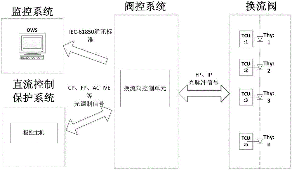
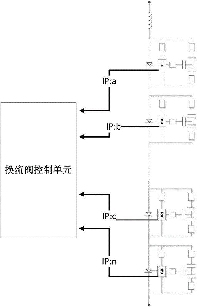
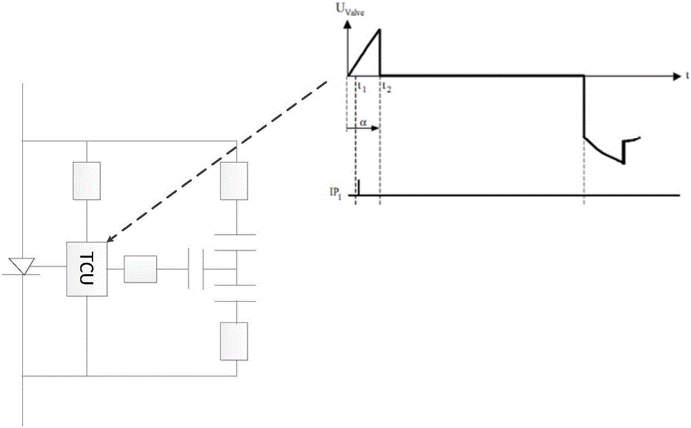
[0025] The invention provides a statistical method for the consistency of the pressure equalization state of a converter valve, and the realization carrier is a converter valve control unit, which is the core key equipment of the whole converter valve control system. The structure diagram of the converter valve control system is as follows: figure 1shown. The converter valve control system realizes the control function of the converter valve under various operating conditions. The converter valve control system is mainly composed of a DC control protection system, a converter valve control unit and a thyristor control unit. Among them, the converter valve control unit is the bridge between the DC control and protection system and the converter valve. Its main function is to receive the control signals ...


PUM


Abstract

The invention discloses a converter valve voltage-sharing state consistency statistics method, which includes the following steps of: configuring a register array which is used for storing deviation data for each thyristor valve level of the converter valve in a converter valve control unit, and configuring a storage region for storing the deviation data with time mark information; configuring a high speed processor in the converter valve control unit as a key core device; designing a deviation data screening algorithm in the converter valve control unit used for screening the data with large deviation from state signals fed back from the each thyristor control unit of the converter valve, and classifying and storing the data; designing and providing an interface for reading the deviation data in the converter valve control unit, the interface being used for on-line monitoring the deviation data or reading the data and off-line analyzing the data; and finding the thyristor valve level with large deviation accumulation quantity from a data statistics result, analyzing a specific location in a thyristor valve voltage-sharing loop where the difference exists, thereby pre-judging the case that this type of thyristor valve level may have fault, and taking the pre-judgment as a reference basis of device replacement and optimization design.

Description

technical field [0001] The invention belongs to the field of high-power electric power electronics, and in particular relates to a statistical method for the consistency of the pressure equalization state of a converter valve. Background technique [0002] High voltage direct current transmission (High Voltage Direction Current, HVDC) is the most important, the most traditional, and the most active technology in the application of power electronics technology. As the core primary equipment in the HVDC transmission project, the converter valve's working performance is directly related to the stability of the HVDC transmission operation. The control function of the converter valve under various operating conditions is completed by the converter valve control system. The converter valve control system is mainly composed of a DC control protection system, a converter valve control unit (ValveControlUnit, VCU) and a thyristor control unit (ThyristorControlUnit, TCU). Among them...

Claims


Application Information

Patent Timeline
Patent Type & Authority Applications(China)
IPC IPC(8): H02J13/00G01R31/08
CPCH02J13/0062G01R31/088H02J13/00001H02M1/088H02M1/32H02M7/7575Y02E60/60G01R31/08G01R31/40G08B21/185H02J13/00Y04S10/20Y02E60/00
Inventor 高晟辅方太勋王永平张翔潘卫明袁明周谷庆
Owner NR ELECTRIC CO LTD
Learn More