
Germanium tetraflouride and hydrogen mixtures for an ion implantation system

A technology of ion implantation and germanium tetrafluoride, which is applied in ion implantation plating, electrical components, vacuum evaporation plating, etc., can solve the problems of shortened service life, reduced arc current of ion source, reduced performance and service life of ion source, etc. problems, to achieve the effect of reducing coating or deposition

Pending Publication Date: 2020-12-18
ENTEGRIS INC
View PDF6 Cites 0 Cited by
  • Summary
  • Abstract
  • Description
  • Claims
  • Application Information

AI Technical Summary

Problems solved by technology

[0007] Ion source failures can be attributed to a variety of causes, including the accumulation of deposits on the cathode surface that negatively affect the thermionic emission of the ions, resulting in reduced arc current, reduced performance, and reduced service life of the ion source, and due to Production of free fluorine from deleterious etching reactions of such dopant gases as germanium tetrafluoride, and stripping of cathode material leading to loss of physical integrity of the cathode and consequent reduction in performance and useful life of the ion source or sputtering

Method used


Image

  • Germanium tetraflouride and hydrogen mixtures for an ion implantation system
  • Germanium tetraflouride and hydrogen mixtures for an ion implantation system
  • Germanium tetraflouride and hydrogen mixtures for an ion implantation system

Examples


example 1

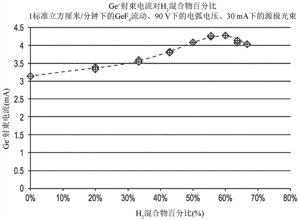
[0085] Use GeF 4 / H 2 Ion implantation of mixtures (beam current)

[0086] An ion implantation apparatus having the following features: The implant test vertical of an indirectly heated cathode (IHC) source with a tungsten arc chamber and liner was under an arc voltage (ArcV) of 90V and a source beam of 30mA operate. into the GeF implanted in the chamber 4 The flow was maintained at a constant rate of 1 sccm. to the H in the chamber 2 The mix varies from 0% to 67%. With the H in the chamber 2 The beam current is measured as the percentage of the mixture is varied. The results are shown in image 3 middle.

example 2

[0088] Use GeF 4 / H 2 Ion implantation of the mixture (cathode weight change)

[0089] The ion implanter according to Example 1 was operated at various arc voltages (ArcV) at 90V, 75V and 60V and source beam at 30mA. into the GeF implanted in the chamber 4 The flow was maintained at a constant rate of 1 sccm. to the H in the chamber 2 The percentage mixture varies from 0% to 56%. The rate of weight change (grams / hour) of the cathode was measured after the run period. The results are shown in Figure 4 middle.

example 3

[0091] Use GeF 4 / H 2 Ion implantation of mixtures (beam spectroscopy)

[0092] The ion implanter according to Example 1 was operated at an arc voltage of 90 V and a source beam of 30 mA. into the GeF implanted in the chamber 4 The flow was maintained at a constant rate of 1 sccm. to the H in the chamber 2 The percentage mixture was varied at 0%, 50% and 67%. AMU beam spectroscopy is performed, allowing comparison of changes in beam current for various ion species. The results are shown in Figure 5 middle.

[0093] aspect

[0094] Aspect 1. A method for providing an ion implantation chamber containing germanium tetrafluoride (GeF 4 ) and hydrogen (H 2 ) a gas mixture of gases to a first gas supply assembly comprising: one or more 4 and H 2 A fluid supply package, wherein the assembly is configured to provide a GeF-containing 4 with H 2 gas mixture, where H 2 present in an amount ranging from 25% to 67% by volume of the gas mixture, or GeF 4 and H 2 With vol...


PUM


Abstract

The current disclosure is directed to methods and assemblies configured to deliver a mixture of germanium tetrafluoride (GeF4) and hydrogen (H2) gases to an ion implantation apparatus, so H2 is present in an amount in the range of 25%-67% (volume) of the gas mixture, or the GeF4 and H2 are present in a volume ratio (GeF4:H2) in the range of 3:1 to 33:67. The use of the H2 gas in an amount in mixture or relative to the GeF4 gas prevents the volatilization of cathode material, thereby improving performance and lifetime of the ion implantation apparatus. Gas mixtures according to the disclosure also result in a significant Ge+ current gain and W+ peak reduction during an ion implantation procedure.

Description

[0001] Cross References to Related Applications [0002] This application claims the benefit of U.S. Provisional Application No. 62 / 672,879, filed May 17, 2018, which is hereby incorporated by reference in its entirety for all purposes. technical field [0003] The present disclosure relates to germanium tetrafluoride and hydrogen gas mixtures for enhanced lifetime and performance of components of ion implantation systems. Background technique [0004] Ion implantation as practiced in semiconductor manufacturing involves depositing chemical species into a substrate, such as a microelectronic device wafer, by impacting energetic ions of such species on the substrate. In order to generate ion-implanted species, a dopant gas, which may be, for example, a halide or hydride of the dopant species, is subjected to ionization. This ionization is performed using an ion source to generate an ion beam. [0005] Once generated at the ion source, the ion beam is processed through extr...

Claims


Application Information

Patent Timeline
Patent Type & Authority Applications(China)
IPC IPC(8): C23C14/48H01J37/317H01J37/08
CPCC23C14/48H01J2237/006H01J2237/0213H01J37/3171H01J37/08C23C14/228C23C14/564H01J2237/022
Inventor S·N·叶达弗O·比尔唐瀛J·R·德普雷斯J·D·斯威尼
Owner ENTEGRIS INC
Learn More