Forced guiding multistage rotation pressing flame ash separating structure for cooking furnace

A technology of forced orientation and separation structure, which is applied in the direction of household stoves/stoves, lighting and heating equipment, solid heating fuels, etc. It can solve the problems of heat loss, reduction of thermal efficiency of finishing, and treatment of light ash and slag, and achieve an increase in heat exchange rate Effect

Active Publication Date: 2016-06-29
平邑经发科技服务有限公司
View PDF5 Cites 3 Cited by
  • Summary
  • Abstract
  • Description
  • Claims
  • Application Information

AI Technical Summary

Problems solved by technology

[0002] In the prior art, there are a variety of combustion devices using biomass fuels. These devices have improved the slag removal and air supply to a certain extent, so that the thermal efficiency has increased, but none of them has treated the small amount of light weight contained in the hot gas stream. Most of the light ash generated after combustion will be discharged from the flue through the air-inducing device, and the other part will be discharged from the pot circle with the flame, thus causing a certain degree of pollution to the room
At the same time, due to the existence of the air induction device, part of the heat is bound to be lost, resulting in a reduction in the thermal efficiency of finishing.
[0003] To sum up, although the combustion device in the prior art is low in use cost and its thermal efficiency can meet daily use, it still has certain limitations because it does not treat the ash that can be discharged into the air.

Method used


Image

  • Forced guiding multistage rotation pressing flame ash separating structure for cooking furnace
  • Forced guiding multistage rotation pressing flame ash separating structure for cooking furnace

Examples


specific Embodiment approach

[0011] Specific implementation manners: the present application is not limited by the following examples, and specific implementation manners can be determined according to the technical solutions of the present invention and actual conditions.

Embodiment

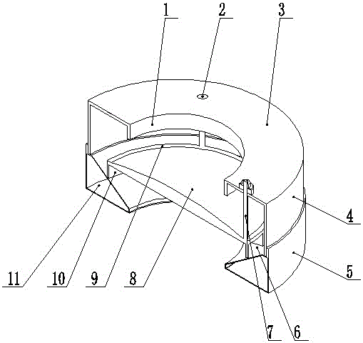
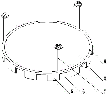
[0012] Example: such as figure 1 As shown, the forced-guided multi-stage rotary pressing fire ash separation structure of the cooking stove includes a flame collection box 11, which is a cavity ring, and a cavity secondary guide ring for guiding the direction of the flame is communicated above it. A primary deflector for dispersing flames is arranged between the secondary deflector ring and the flame collection box 11 . The secondary diversion ring includes diversion inner and outer rings 1 and 4, and the upper ends of the diversion inner and outer rings 1 and 4 are covered with a secondary diversion cover plate 3, and the primary diversion plate includes an annular ring frame 9. A first-stage diversion cover plate 8 is arranged inside the ring frame 9 , and a circle of diversion rings 10 is arranged on the outer circumference of the lower end surface of the first-stage diversion cover plate 8 , and diversion ports 6 are provided at equidistant intervals on the diversion ring ...


PUM


Abstract

The invention relates to a forced guiding multistage rotation pressing flame ash separating structure for a cooking furnace. The forced guiding multistage rotation pressing flame ash separating structure comprises a flame collecting box which is in a cavity ring shape. A cavity second-stage flow guiding ring used for guiding the moving direction of flames communicates with the upper portion of the flame collecting box. A first-stage flow guiding plate used for scattering the flames is arranged between the second-stage flow guiding ring and the flame collecting box. The position of an inner opening of the flame collecting box is shielded through the first-stage flow guiding plate. Due to the graded flow guiding of the first-grade flow guiding plate and the second-stage flow guiding plate, light ash contained in the flames can be thoroughly knocked off, and the structure can be applied and popularized in any industry needing cooking, usable scenes the same as traditional energy such as electric heat, gas, fuel, fire coal and the like are available, and the structure has the larger excellence in the aspects of safety, flexibility and energy loss ratios. An opened type natural convection semi-gasification combustion manner is adopted, heat energy is directly transmitted to a container for heating to the maximum, forced flow guiding through an induced draught fan is avoided, heat energy cannot be lost, and the heat exchange efficiency is greatly improved.

Description

technical field [0001] The present application relates to a soot cleaning structure, in particular to a forced-guided multi-stage rotary pressing fire ash separation structure for cooking stoves used in cooking stoves. Background technique [0002] In the prior art, there are a variety of combustion devices using biomass fuels. These devices have improved the slag removal and air supply to a certain extent, so that the thermal efficiency has increased, but none of them has treated the small amount of light weight contained in the hot air flow. Most of the light ash generated after combustion will be discharged from the flue through the air-inducing device, and the other part will be discharged from the pot circle with the flame, thus causing a certain degree of indoor pollution. At the same time, due to the existence of the air-inducing device, a part of heat is bound to be lost, resulting in a reduction in the thermal efficiency of finishing. [0003] To sum up, although t...

Claims


Application Information

Patent Timeline
Patent Type & Authority Applications(China)
IPC IPC(8): F24B13/00
CPCF23J1/02F24B13/006
Inventor 谢秋华刘伟民孔准初
Owner 平邑经发科技服务有限公司
Why Eureka
Try Eureka