
Variable bandwidth linear phase filter method based on Laplace structure

A linear phase and filter technology, applied in the field of signal processing, can solve the problems that the fully reconstructed filter bank is difficult to have linear phase characteristics, it is difficult to achieve variable bandwidth and linear phase at the same time, and the filter bank is difficult to achieve.

Active Publication Date: 2018-08-17
XIDIAN UNIV
View PDF2 Cites 0 Cited by
  • Summary
  • Abstract
  • Description
  • Claims
  • Application Information

AI Technical Summary

Problems solved by technology

In the design of a fully reconstructed filter bank, although the linear phase characteristic is easy to achieve in a two-channel filter bank, it is often difficult to achieve in a multi-channel fully reconstructed filter bank, resulting in a bandwidth of Except for the dual-channel filter bank, it is difficult for the fully reconstructed filter bank of other bandwidths to have linear phase characteristics
Therefore, in the Laplacian pyramid structure LP, this indirect filter design method taken from the fully reconstructed filter bank will cause the filter in the Laplacian pyramid structure LP to be fully reconstructed filtering It is difficult to achieve variable bandwidth and lack of linear phase at the same time due to the limitation of the device group

Method used


Image

  • Variable bandwidth linear phase filter method based on Laplace structure
  • Variable bandwidth linear phase filter method based on Laplace structure
  • Variable bandwidth linear phase filter method based on Laplace structure

Examples


example 1

[0075] Example 1: Designing a bandwidth based on the Laplace structure is A low-pass filter of length 24.

[0076] This example includes the low-pass synthesis filter g L The design and analysis of the low-pass filter h L The design has two parts. 1. Design a low-pass reconstruction filter g L

[0077] Step 1, set the low-pass synthesis filter g L parameters.

[0078] Let length N L =24, sampling factor M=4, passband cut-off frequency stop band start frequency where r L is the low-pass transition band adjustment parameter, by changing r L The size of the transition zone can be easily adjusted. In this example, r L = 0.4.

[0079]Step 2, determine the low-pass prototype filter p L .

[0080] low-pass prototype filter p L is essentially a low-pass impulse response sequence p L (n), this example obtains the linear phase low-pass prototype filter p by calling the firpm function in MatLab L The impulse response sequence p L (n),n=0,1,...N L -1.

[0081] The f...

example 2

[0110] In Example 2, the bandwidth based on the Laplace structure is A bandpass filter of length 60.

[0111] This example includes a pair of bandpass synthesis filters g B The design and analysis of the bandpass filter h B The design has two parts. 1. Design a bandpass synthesis filter g B

[0112] Step 1, set the band-pass synthesis filter g B parameters.

[0113] Let length N B =60, the sampling factor M=3, and the passband cut-off frequencies are The start frequency of the stop band is where r B is the band-pass transition band adjustment parameter, by changing r B The size of the transition zone can be easily adjusted, this real r B = 0.3.

[0114] Step 2, determine the bandpass prototype filter p B .

[0115] bandpass prototype filter p B is essentially a bandpass impulse response sequence p B (n), this example obtains the linear phase bandpass prototype filter p by calling the firpm function in MatLab B The impulse response sequence p B (n),n=0,1,...

example 3

[0142] Example 3. Design the bandwidth based on the Laplace structure as A high-pass filter of length 60.

[0143] This example includes the high-pass synthesis filter g H The design and analysis of the high-pass filter h H The design has two parts. 1), design high-pass synthesis filter g H

[0144] Step A, set the high-pass synthesis filter g H parameters.

[0145] Let length N H =60, sampling factor M=3, passband cut-off frequency stop band start frequency where r H is the high-pass transition band adjustment parameter, by changing r H The size of the transition zone can be easily adjusted. In this example, r H = 0.2.

[0146] Step B, determine the high-pass prototype filter p H .

[0147] High-pass prototype filter p H is essentially a high-pass impulse response sequence p H (n), this example obtains the linear phase high-pass prototype filter p by calling the firpm function in MatLab H The impulse response sequence p H (n),n=0,1,...,N H -1.

[0148] ...


PUM


Abstract

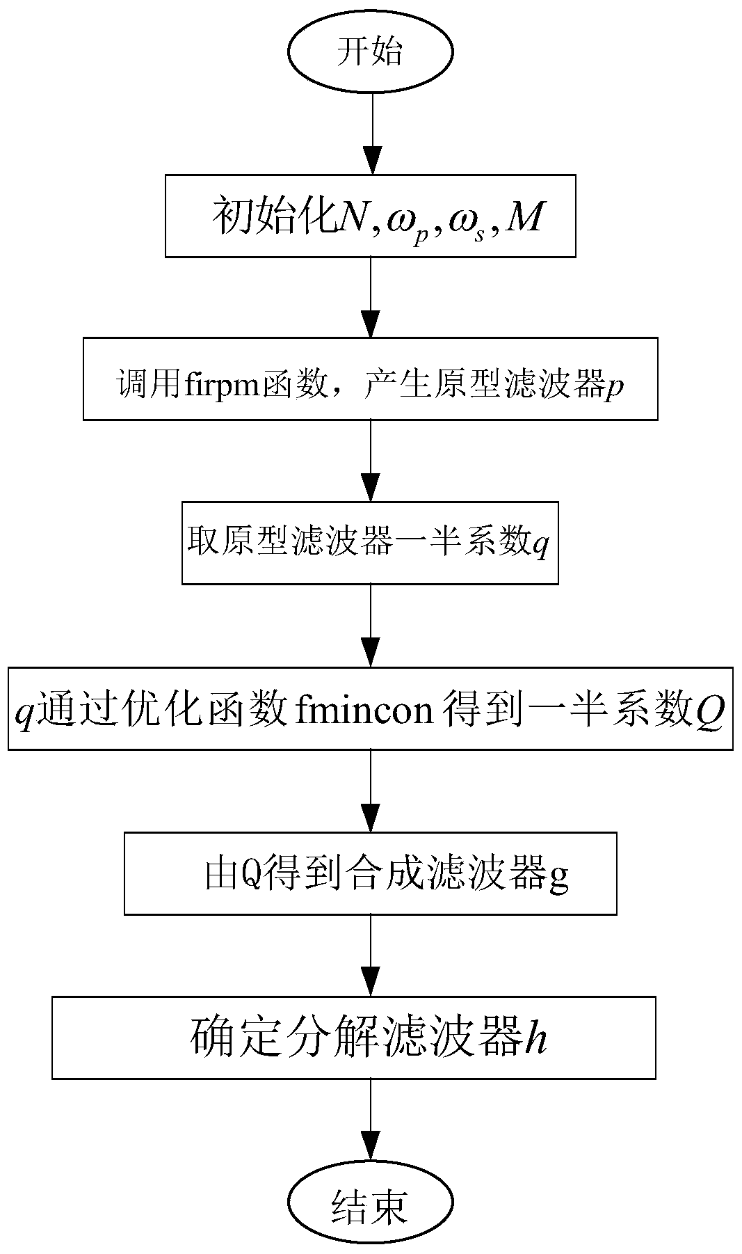
The invention discloses a design method for a filter suitable for a Laplacian pyramid structure. It mainly solves the problem that in the existing Laplacian pyramid structure filters, except for the Haar filter, other filters cannot have linear phases at the same time. and orthogonal properties. The technical solution is: first set the filter length N, the passband cutoff frequency ωp and the stopband starting frequency ωs, and the sampling factor M; then based on these parameters, call the firpm function in MatLab to generate a prototype filter p; for the prototype Half of the coefficients of the filter are optimized by calling the fmincon function, and the synthetic filter is obtained based on the optimization results; finally, the decomposed filter can be obtained based on the time domain flip relationship. By providing a reasonable orthogonal constraint condition, the present invention not only enables the filter to have orthogonal and linear phase characteristics, but also has variable bandwidth, thereby providing wider application conditions for the Laplacian pyramid structure filter.

Description

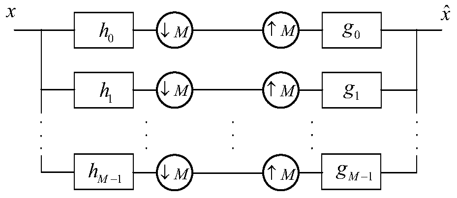
technical field [0001] The invention belongs to the technical field of signal processing, and in particular relates to a design method of a linear phase filter with variable bandwidth, which can be used for image fusion, addition, compression, denoising and edge detection. Background technique [0002] The Laplacian pyramid structure LP was first proposed by Burt et al., and was originally used for image coding and compression. Later, people extended the Laplacian pyramid structure LP into a multi-scale and multi-resolution analysis tool, which is applied to many fields of image processing, such as image fusion, image denoising, etc. [0003] figure 1 The structure diagram of Laplacian pyramid is given. exist figure 1 , for a given input signal x, the output c is an approximate approximation of x, and d is the residual between the original signal and its predicted signal p. In this structure, the analysis filter h and the synthesis filter g are usually a pair of low-pass...

Claims


Application Information

Patent Timeline
Patent Type & Authority Patents(China)
IPC IPC(8): G06T5/00G06T7/13H03H17/00
CPCH03H17/00G06T2207/20182G06T2207/20221H03H2017/0081G06T5/70
Inventor 谢雪梅翁昕张亚中赵至夫邓廷廷
Owner XIDIAN UNIV
Learn More