Integrated magnetic coupled inductor in the shape of Chinese character mu

A technology of coupled inductance and magnetic integration, applied in the field of inductors, can solve the problems of reducing the volume loss of the magnetic core, long mutual inductance magnetic path of the two coils, small self-inductance and mutual inductance, etc., so as to reduce the electromagnetic loss and increase the self-inductance. value and coupling coefficient, the effect of planarization for high efficiency

Active Publication Date: 2016-06-29
杨玉岗
View PDF6 Cites 1 Cited by
  • Summary
  • Abstract
  • Description
  • Claims
  • Application Information

AI Technical Summary

Problems solved by technology

The existing "EE" or "EI" type coupled inductors have technical defects such as the long mutual inductance magnetic path of the two coils, large m

Method used


Image

  • Integrated magnetic coupled inductor in the shape of Chinese character mu
  • Integrated magnetic coupled inductor in the shape of Chinese character mu
  • Integrated magnetic coupled inductor in the shape of Chinese character mu

Examples


Embodiment 1

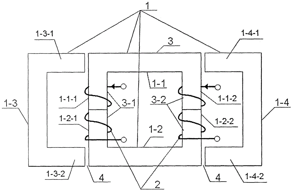
[0026] Refer to attached figure 1 , a "mesh"-shaped magnetically integrated coupled inductor, which is composed of a "mesh"-shaped iron core body 1 and a two-phase coil 2, and the iron core body 1 is composed of four "U"-shaped iron cores 1-1, 1- 2. Composed of 1-3 and 1-4; the magnetic columns 1-1-1, 1-1-2 and 1-2-1 of the two "U" shaped iron cores 1-1 and 1-2, 1-2-2 are relatively placed to form a "mouth"-shaped iron core 3, and the magnetic columns 1-1-1 and 1-2-1 of the two "U"-shaped iron cores 1-1 and 1-2 are opposite to each other , 1-1-2 and 1-2-2 relatively form the two magnetic columns 3-1 and 3-2 of the "口"-shaped iron core 3; The two-phase coils 2 are respectively wound on two magnetic columns 3-1 and 3-2; the other two "U"-shaped iron cores 1-3 and 1-4 are respectively placed on the "mouth"-shaped iron cores The two sides of the magnetic columns 3-1 and 3-2 of 3 are buckled on the two-phase coil 2; the magnetic columns 1-3- of the other two "U" shaped iron cores...

Embodiment 2

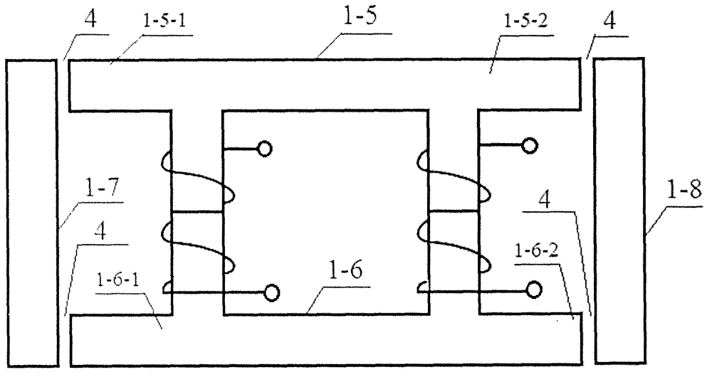
[0028] Refer to attached figure 2 , another application embodiment of a "mesh"-shaped magnetically integrated coupled inductor, the "U"-shaped iron cores 1-1, 1-2 in the first embodiment are replaced with Font iron core 1-5, 1-6, "U" font iron core 1-3, 1-4 in embodiment one is replaced with " I " font iron core 1-7, 1-8; " I " font Iron core 1-7, 1-8 respectively with A distance is maintained between the yokes 1-5-1 and 1-6-1, 1-5-2 and 1-6-2 of the glyph iron cores 1-5 and 1-6 to form an air gap 4 .

Embodiment 3

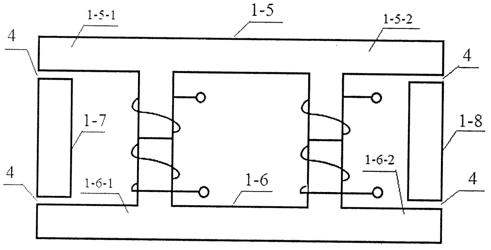
[0030] Refer to attached image 3 , another application embodiment of a "mesh"-shaped magnetically integrated coupled inductor, the "I"-shaped iron core 1-7 in the second embodiment is sandwiched between Between the yokes 1-5-1 and 1-6-1 of the glyph iron core 1-5, 1-6, the "I" glyph iron core 1-8 in the embodiment two is sandwiched Between the yoke 1-5-2 and 1-6-2 of font iron core 1-5,1-6; " I " font iron core 1-7,1-8 and A distance is maintained between the yokes 1-5-1 and 1-6-1, 1-5-2 and 1-6-2 of the glyph iron cores 1-5 and 1-6 to form an air gap 4 .


PUM


Abstract

The invention discloses an integrated magnetic coupled inductor in the shape of Chinese character mu, wherein the inductor is composed of an iron core body in the shape of Chinese character mu and two-phase coils; the iron core body in the shape of Chinese character mu is composed of four ''U'' shaped iron cores; the magnetic poles of two ''U'' shaped iron cores are arranged oppositely and form a square shaped iron core; the two-phase coils are wound on the two magnetic poles of the square shaped iron core; the other two ''U'' shaped iron cores are arranged at two sides of the magnetic poles of the square shaped iron core and are buckled on the two-phase coils; and the two magnetic poles of the other two ''U'' shaped iron cores keep certain distances with the magnetic poles of the square shaped iron core, thus forming air gaps. The inductor has the advantages that the inductor is used for inductance coupling integration; the quantity of the air gaps is doubled; the lengths of the air gaps are reduced to a half; the air gaps are symmetrical; the diffusion fluxes of the air gaps are clearly reduced; the mutual inductive magnetic circuit of the two coils is the shortest without the air gap; the mutual inductance and the self-inductance are high; the energy and the material are saved; and the electromagnetic interferences are reduced.

Description

technical field [0001] The invention relates to an inductor, in particular to a "me"-shaped magnetic integrated coupling inductor, which can be widely used in various interleaved parallel switching power supplies with one-way operation and two-way operation. technical background [0002] In recent years, switching power supplies that provide electrical energy for various electrical equipment are developing in the direction of low voltage, high current, small size, light weight, high efficiency, thinning and integration, including the widely used in electric vehicles that have emerged in recent years , hybrid vehicles, uninterruptible power supplies, power quality regulation power supplies, aviation power supplies, renewable energy power generation and superconducting energy storage and other bidirectional switching power supplies that require bidirectional energy flow. These switching power supplies use a multi-phase interleaved parallel topology. It can increase the output ...

Claims


Application Information

Patent Timeline
IPC IPC(8): H01F17/04H01F27/24H01F3/14
Inventor 杨玉岗张凯强
Owner 杨玉岗
Why Eureka
Try Eureka