
Method for grinding spring ends and spring-end grinding machine

A grinding machine and grinding technology, which is applied to machine tools suitable for grinding workpiece planes, parts of grinding machine tools, grinding/polishing equipment, etc. The effect of avoiding overheating and eliminating cooling measures

Active Publication Date: 2016-06-29
WAFIOS AKTIENGES
View PDF11 Cites 0 Cited by
  • Summary
  • Abstract
  • Description
  • Claims
  • Application Information

AI Technical Summary

Problems solved by technology

However, the grinding power is limited by the permissible temperature of the spring material and the power of the grinding disc

Method used


Image

  • Method for grinding spring ends and spring-end grinding machine
  • Method for grinding spring ends and spring-end grinding machine
  • Method for grinding spring ends and spring-end grinding machine

Examples


Embodiment Construction

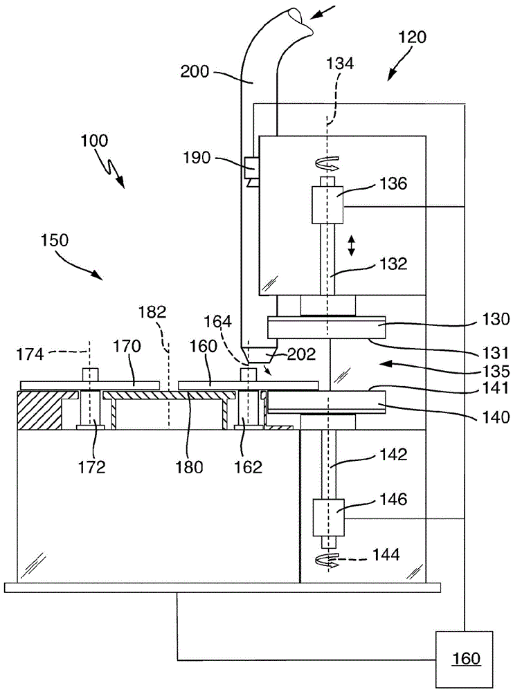
[0053] Particular aspects of embodiments of the invention are illustrated below, taking as an example a spring end grinder 100 in a vertical configuration, which uses a double-sided face grinding method in the feed method, utilizing Preloaded spring settings are used for dry machining of helical compression springs (also called springs for short). The machine is constructed with two grinding spindles and two load discs in a single construction. The machine basically comprises a grinding unit 120 , a load unit 150 and a control unit 160 for controlling the controllable components of load unit 150 and grinding unit 120 .

[0054] The grinding unit 120 has a grinding disc pair with two coaxially rotatable grinding discs 130 , 140 , between which a grinding space 135 is formed during operation of the machine. The upper grinding disc 130 is fastened to the lower end of an upper grinding shaft 132 , which is mounted with a vertical axis of rotation 134 in the upper part of the supp...


PUM


Abstract

The invention relates to a method for grinding spring ends of helical compression springs using a numerically controlled spring-end grinding machine (100) having a grinding unit (120), a loading unit (150) and a control unit (160) for controlling the loading unit (150) and the grinding unit (120). The grinding unit (120) has a grinding disc pair with two rotatable grinding discs (130, 140), between which a grinding space (135) is formed. The loading unit (150) has at least one loading plate (160, 170), which is rotatable substantially axially parallel to the grinding discs (130, 140) and has a plurality of off-axial spring receptacles (166), each for receiving a respective helical compression spring (F). During a grinding operation, helical compression springs (F) received in spring receptacles (166) are successively transported through the grinding space between the rotating grinding discs (130, 140) by rotation of the loading plate (160, 170) and in the process both spring ends of the helical compression springs (F) located in the grinding space are simultaneously machined by grinding. The method is characterized in that a temperature signal representing the temperature is determined on at least one of the helical compression springs (F) by a temperature measurement during the grinding operation. The spring-end grinding machine (100) is preferably controlled on the basis of the temperature signal. In one embodiment, the temperature is measured using a thermal imaging camera (190). The temperature measuring device (190) is arranged in a cooling air supply duct (200) belonging to a cooling device and / or in a cooling air stream generated by the supply duct (200).

Description

technical field [0001] The invention relates to a method for grinding a spring end of a helical compression spring according to the preamble of claim 1 and to a spring according to the preamble of claim 14 which is especially suitable for carrying out said method End grinder. Background technique [0002] Helical compression springs are machine elements which are required in a large number of fields of application, in large quantities and in different designs. Helical compression springs are required in large quantities in automobile construction, for example as load springs or valve springs. A helical compression spring can be described as a helical or coiled compression spring formed from a wire with a spacing between the helices. [0003] In normal use, the spring ends, that is to say the two axial end regions of the compression helical spring, are particularly relevant for the securing function of the compression helical spring. The spring ends are used to transmit th...

Claims


Application Information

Patent Timeline
IPC IPC(8): B24B7/16B24B7/17B24B49/14B24B55/02
CPCB24B7/167B24B7/17B24B49/14B24B55/02
Inventor K.武尔斯特J.沃尔夫M.施尼茨勒
Owner WAFIOS AKTIENGES
Learn More