Measurement method and system for narrow gap welding temperature field

A welding temperature and measurement method technology, applied in the field of measurement, can solve problems such as inaccurate measurement of the welding temperature field, and achieve the effects of improving accuracy, welding efficiency, and convenient operation

Inactive Publication Date: 2017-10-24
HARBIN UNIV OF SCI & TECH
View PDF6 Cites 2 Cited by
  • Summary
  • Abstract
  • Description
  • Claims
  • Application Information

AI Technical Summary

Problems solved by technology

[0005] In view of the shortcomings of the prior art described above, the purpose of the present invention is to provide a method for measuring the temperature field of narrow gap welding, which is used to solve the problem of inaccurate measurement of the welding temperature field of narrow gap welding in the prior art

Method used


Image

  • Measurement method and system for narrow gap welding temperature field
  • Measurement method and system for narrow gap welding temperature field
  • Measurement method and system for narrow gap welding temperature field

Examples


Embodiment 2

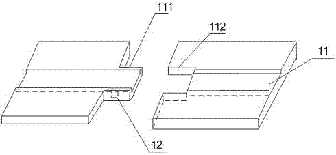
[0060] like figure 2 and 6 As shown, the present invention provides a measurement system for a narrow gap welding temperature field. The measurement system includes: a test board and test equipment 14 .

[0061] The test board includes: narrow-gap weld beads 11 , dividing traces 13 , and thermal induction devices 12 .

[0062] The narrow gap weld bead 11 usually has a width between 18-22 mm.

[0063] The dividing marks 13 are formed by cutting the test plate into two parts along the direction perpendicular to the narrow gap weld bead 11 and then splicing them together, one part of which includes extending along the weld bead 11 and crossing the weld bead. The other part of the convex part 111 of 11 includes a concave part 112 matched with the convex part 111 .

[0064] Take the offshore platform rack steel DILLIMAX690E (see Table 1 and Table 2 for chemical composition and mechanical properties) produced by German Dillingen Metallurgical Company as an example.

[0065] Ta...


PUM

PropertyMeasurementUnit
microhardnessaaaaaaaaaa

Abstract

The invention provides a method and system for measuring narrow gap welding temperature fields. The method comprises the following steps: cutting off a test board into two parts in a narrow gap welding bead direction perpendicular to the test board, wherein one part comprises a projection which extends out along a welding bead and stretches across the welding bead; burying at least one heat induction device towards a heat affected zone of the welding bead and on at least one side vertical face of the projection in the welding bead direction; piecing the two cut parts together to obtain the test board of the heat induction devices buried in the heat affected zone; welding the welding bead of the test board layer by layer according to the preset test pre-arranged planning; and measuring change conditions of temperature fields of the heat affected zone according to the acquired temperature information of the various heat induction devices in a test process. By the method and system for measuring the narrow gap welding temperature fields, electric arc generated on cracks of the welding bead can be effectively prevented from affecting the temperature information induced by the heat induction devices in a welding process, and therefore, the shortcoming that the temperature of the heat affected zone cannot be measured directly by the heat induction devices can be overcome.

Description

technical field [0001] The invention relates to a measurement technology, in particular to a measurement method and system for a narrow gap welding temperature field. Background technique [0002] Metal plates with narrow gap welds are mostly used in large equipment structures such as ships. Because the weld bead chamfer is nearly 90 degrees, it can effectively prevent the consumption of the upper layer of solder. [0003] Accurately measuring the thermal cycle curve of the heat affected zone (HAZ) of the weld bead is the basis for the study of welding metallurgy analysis, welding stress-strain and elastoplastic dynamic analysis, and is also the premise of welding numerical simulation calculation and welding process control. As an efficient method to realize the welding of large and thick plate structural parts, narrow gap welding has technical and economic advantages such as shortening welding time, reducing filling materials and saving energy consumption. At the same time...

Claims


Application Information

Patent Timeline
Patent Type & Authority Patents(China)
IPC IPC(8): B23K9/095
CPCB23K9/0956
Inventor 兰虎王桂军张华军田小林侯军强林尚扬
Owner HARBIN UNIV OF SCI & TECH
Why Eureka
Try Eureka