Hydraulic injection mold

A mold and oil pressure technology, which is applied in the field of hydraulic injection molds, can solve the problems of undesigned uniform distribution channels, uneven liquid glue volume, uneven heating of liquid glue, etc., to achieve the advantages of reduced defect rate, easy control, and high injection molding precision Effect

Active Publication Date: 2018-08-31
DONGGUAN BITE SILICONE RUBBER MOLD CO LTD
View PDF6 Cites 0 Cited by
  • Summary
  • Abstract
  • Description
  • Claims
  • Application Information

AI Technical Summary

Problems solved by technology

[0004] In the existing injection mold, the inside of the mold is a single-layer structure, and the injection part and the molding part are connected together. This structure has the following defects: 1) The newly injected liquid glue enters the mold and is heated unevenly, and the molding effect is not good ;2) The liquid glue in the mold is heated unevenly, resulting in slow product molding efficiency; 3) There is no uniform shunt channel designed, and the liquid glue directly enters the mold hole, resulting in uneven injection of liquid glue during injection molding, resulting in product defect rate increase

Method used


Image

  • Hydraulic injection mold
  • Hydraulic injection mold
  • Hydraulic injection mold

Examples


Embodiment Construction

[0021] The present invention will be further described in detail below in conjunction with the accompanying drawings and specific embodiments.

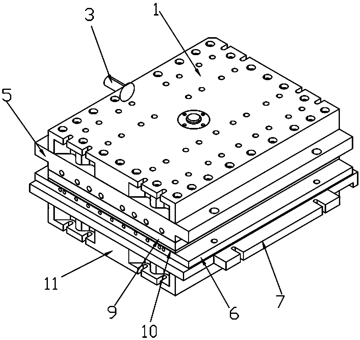
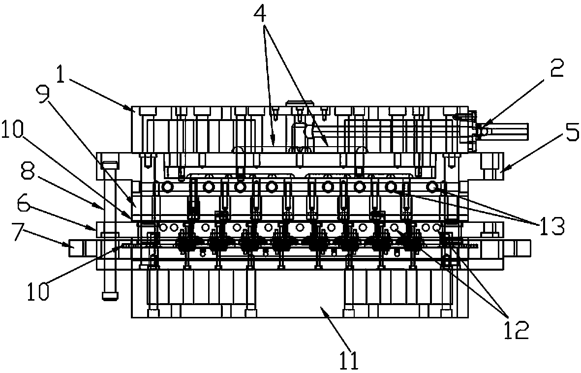
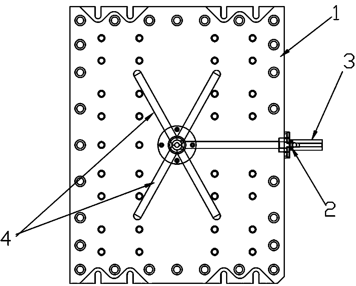
[0022] In this embodiment, refer to Figure 1 to Figure 5 , its specific implementation of the hydraulic injection mold includes a backing plate 11 and a molding module set on the top of the backing plate 11, the top of the molding module is provided with an injection plate 1 for injecting liquid glue, and the side of the injection plate 1 is provided with There are injection ports 3, such as image 3 As shown, the injection port 3 is provided with a one-way valve 2, and the one-way valve 2 includes a one-way passage and a ball for sealing the one-way passage.

[0023] The forming module includes a binder plate 5, a middle plate, a male mold and a female mold 6, the middle plate is installed on the top of the backing plate 11, the male mold is paired and installed on the bottom surface of the middle plate, and the female mold 6 is pa...


PUM


Abstract

The invention relates to an oil pressure injection mold and belongs to the field of silicone product molds. The oil pressure injection mold comprises a base plate and a forming mold set arranged at the top of the base plate. A material injection plate used for injecting a glue solution in is arranged at the top of the forming mold set. Glue injection openings are formed in the side face of the material injection plate. The forming mold set comprises a material pressing plate, a middle plate, a male mold and a female mold. Main channels communicating with the glue injection openings are formed in the material injection plate. A flow channel plate is arranged between the material injection plate and the material pressing plate and provided with a plurality of distributing channels connected with the main channels in a communicating mode. A reinforcing plate and a heat insulating bakelite plate are arranged between the material pressing plate and the female mold. The surface of the reinforcing plate, the surface of the heat insulating bakelite plate and the surface of the material pressing plate are all provided with injection molding channels matched with mold holes in number and position. The heat insulating bakelite plate with good heat insulating effect is additionally arranged, the whole mold is partitioned into a low temperature zone and a high temperature zone through the heat insulating bakelite plate, the effect that the glue solution is not formed due to heating before entering the mold holes is ensured, and therefore the injection efficiency of the glue solution can be improved.

Description

technical field [0001] The invention relates to the field of molds for silicone products, in particular to oil pressure injection molds. Background technique [0002] Injection molding is a tool for producing plastic products, and it is also a tool for giving plastic products a complete structure and precise dimensions. Injection molding is a processing method used in mass production of certain complex-shaped parts. High pressure is injected into the mold cavity, and after cooling and solidification, a molded product is obtained. [0003] The injection mold consists of two parts, the movable mold and the fixed mold. The movable mold is installed on the movable template of the injection molding machine, and the fixed mold is installed on the fixed template of the injection molding machine. During injection molding, the movable mold and the fixed mold are closed to form a gating system and Cavity, when the mold is opened, the movable mold and the fixed mold are separated to t...

Claims


Application Information

Patent Timeline
Patent Type & Authority Patents(China)
IPC IPC(8): B29C45/34B29C45/27B29C45/28B29C45/73B29C37/02
CPCB29C45/0053B29C45/27B29C45/2806B29C45/34B29C45/73B29C2045/0077
Inventor 董恩铭
Owner DONGGUAN BITE SILICONE RUBBER MOLD CO LTD
Why Eureka
Try Eureka