Protective conveying mechanism for high-cleanliness working spaces

A work space, high cleanliness technology, used in conveyors, mechanical conveyors, transportation and packaging, etc., can solve problems such as insufficiency, achieve reasonable structural design, avoid polluting the surrounding environment and materials, and increase manufacturing difficulty and production. cost effect

Active Publication Date: 2016-07-06
SHANGHAI FORTREND TECH CO LTD
View PDF18 Cites 2 Cited by
  • Summary
  • Abstract
  • Description
  • Claims
  • Application Information

AI Technical Summary

Problems solved by technology

[0009] The purpose of the present invention is to provide a protective conveying mechanism for high-cleanliness working space, which overcomes the defect that the existing Cartesian coordinate robot cannot meet the requirements for high-cleanliness working space. The fine dust does not spill out, avoiding the pollution of the surrounding environment and materials. It has a wide range of operations, fast operation speed, and high positioning accuracy, which can meet the requirements of various high-cleanliness work spaces.

Method used


Image

  • Protective conveying mechanism for high-cleanliness working spaces
  • Protective conveying mechanism for high-cleanliness working spaces
  • Protective conveying mechanism for high-cleanliness working spaces

Examples


Embodiment Construction

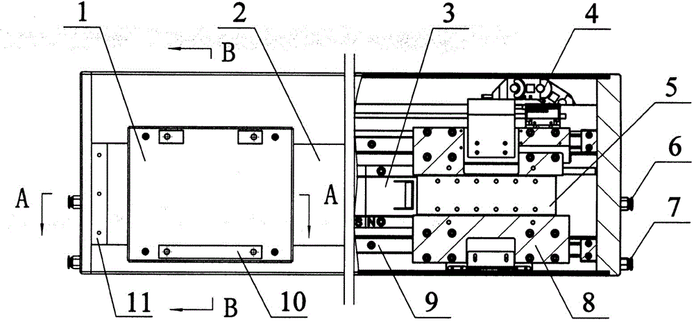
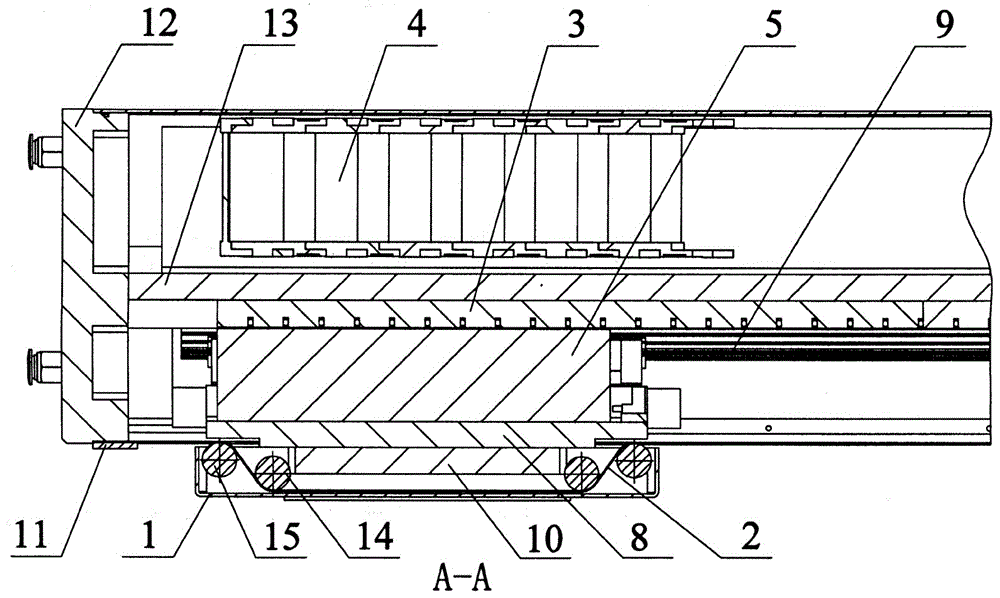
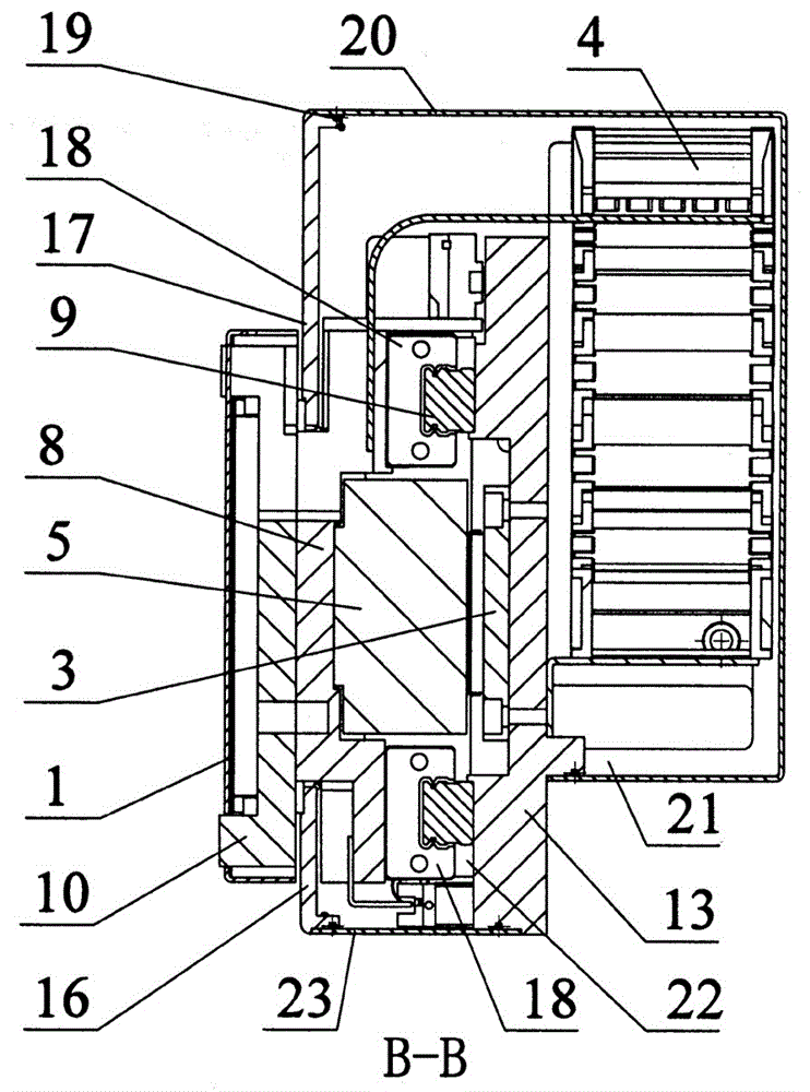
[0025] according to Figure 1~6The specific structure of the present invention will be described in detail. The conveying mechanism used in the high-cleanliness space includes a base body composed of a base plate 13 and a side plate 12 provided with an upper guard plate 17, a lower guard plate 16, an upper cover plate 20, and a lower cover plate 23. A linear motion device that is matched by a linear motor and a linear guide rail 9, the towline cavity air outlet 6 and the guide rail that are provided on the side plate 12 and communicate with the inner cavity of the substrate for connecting to an external negative pressure source (not shown in the figure) Cavity gas outlet 7 etc. pieces. In this embodiment, a linear motor is used as the driving body, and the base plate 13 and the side plates 12 mounted on both sides of the base plate 13 are used as the basic structure of the base of the linear motion device. The stator 3 and the linear guide rail 9 of the linear motor are resp...


PUM


Abstract

Provided is a protective conveying mechanism for high-cleanliness working spaces. The defect that an existing Cartesian-coordinate robot cannot be used for high-cleanliness working spaces is overcome. The protective conveying mechanism for high-cleanliness working spaces is technically characterized in that a unique structure combining sealing and negative pressure adsorption is adopted, that is, a channel opening needed for movement of a rotor of a linear motor and an external standby fixing plate assembled together with a positioning supporting connecting plate is sealed by a dustproof belt; a sealed chamber is formed by an inner cavity of a base body, and a whole driving main body is packaged in the inner cavity of the base body; under the action of negative pressure adsorption in the sealed chamber communicating with an external negative pressure source, generated airflow flows in sequence and is exhausted through a corresponding exhaust opening in the closed chamber, and the effect that micro dust produced by all movement units is not leaked out of the sealed chamber of the base body is guaranteed. The protective conveying mechanism for high-cleanliness working spaces is reasonable in structural design, wide in operation range, high in operation speed, accurate in positioning accuracy and capable of meeting the requirement of various high-cleanliness working spaces, the micro dust produced by the movement units is not leaked out, and the ambient environment and materials are prevented from being polluted.

Description

technical field [0001] The invention relates to a conveying mechanism suitable for materials such as chips and silicon wafers in the semiconductor and solar energy industries, especially a protective conveying mechanism used in high-cleanliness work spaces, and is also suitable for other industries that require a wide range of operations and high operating efficiency. Fast speed, high positioning accuracy, and the cleanliness level is stipulated in the workplace above Class10. Background technique [0002] In the semiconductor or solar industry, it is often necessary to transfer materials in a high-cleanness working space, which requires fast running speed and high positioning accuracy. In order to maintain the cleanliness of the entire working space, the conveying mechanism is required to meet the specified cleanliness requirements, such as Class100, or even Class10. [0003] For this reason, many clean motion mechanisms have emerged as the times require. As reported in t...

Claims


Application Information

Patent Timeline
Patent Type & Authority Applications(China)
IPC IPC(8): B65G35/00
CPCB65G35/00B65G2207/26
Inventor 吴功郑君强
Owner SHANGHAI FORTREND TECH CO LTD
Why Eureka
Try Eureka