Circular ash removing method suitable for fluidized bed boiler

A fluidized bed boiler and fluidized bed technology are applied in the field of ash removal of boiler equipment, which can solve the problems of low output of circulating fluidized bed boilers, influence heat exchange efficiency, poor soot blowing effect, etc., so as to improve soot blowing efficiency and ensure Sandblasting effect, the effect of improving dust removal efficiency

Active Publication Date: 2016-07-06
HMEI THREAD CO LTD OF YINBIN SICHUAN
View PDF10 Cites 3 Cited by
  • Summary
  • Abstract
  • Description
  • Claims
  • Application Information

AI Technical Summary

Problems solved by technology

The high-efficiency energy-saving two-speed circulating fluidized bed boiler disclosed in this patent document is ventilated through the primary air duct and the secondary air duct. Although it can blow away part of the ash particles adhering to the air preheater, it is difficult to blow to the air preheater. The soot in the center of the tube bundle of these heat exchange components is not completely blown, and the soot blowing effect is poor, which affects the heat exchange efficiency, resulting in low output and low efficiency of the entire circulating fluidized bed boiler

Method used


Image

  • Circular ash removing method suitable for fluidized bed boiler
  • Circular ash removing method suitable for fluidized bed boiler
  • Circular ash removing method suitable for fluidized bed boiler

Examples


Embodiment 1

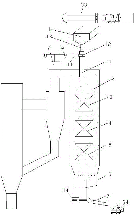
[0067] see figure 1, a circulating ash removal method suitable for a fluidized bed boiler, comprising a sand loading step and a recovery step, a sand blasting step between the sand loading step and the recovery step, and a sand extraction step after the sand blasting step. , the sand loading step refers to that the sand is contained in the sand hopper 1 of the circulating sand soot blowing device; the sand blasting step refers to putting the sand in the sand hopper 1 into the sand blasting device of the circulating sand soot blowing device, The sand blaster sprays the sand into the tail shaft 2 of the fluidized bed boiler; the recovery step refers to that the sand sprayed into the tail shaft 2 washes the superheater 3, the economizer 4 and the air preheater 5 and flows to the circulating sand In the fluidized bed 6 of the soot blowing device, the sand is recovered through the auger 7 connected to the fluidized bed 6; the sand-lifting step means that the sand recovered by the a...

Embodiment 2

[0070] see figure 1 , a circulating ash removal method suitable for a fluidized bed boiler, comprising a sand loading step and a recovery step, a sand blasting step between the sand loading step and the recovery step, and a sand extraction step after the sand blasting step. , the sand loading step refers to that the sand is contained in the sand hopper 1 of the circulating sand soot blowing device; the sand blasting step refers to putting the sand in the sand hopper 1 into the sand blasting device of the circulating sand soot blowing device, The sand blaster sprays the sand into the tail shaft 2 of the fluidized bed boiler; the recovery step refers to that the sand sprayed into the tail shaft 2 washes the superheater 3, the economizer 4 and the air preheater 5 and flows to the circulating sand In the fluidized bed 6 of the soot blowing device, the sand is recovered through the auger 7 connected to the fluidized bed 6; the sand-lifting step means that the sand recovered by the ...

Embodiment 3

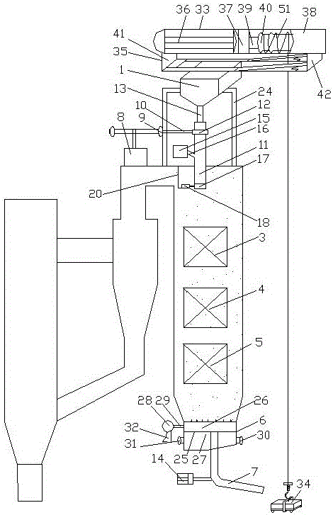
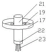
[0077] see figure 2 and image 3 , a circulating ash removal method suitable for a fluidized bed boiler, comprising a sand loading step and a recovery step, a sand blasting step between the sand loading step and the recovery step, and a sand extraction step after the sand blasting step. , the sand loading step refers to that the sand is contained in the sand hopper 1 of the circulating sand soot blowing device; the sand blasting step refers to putting the sand in the sand hopper 1 into the sand blasting device of the circulating sand soot blowing device, The sand blaster sprays the sand into the tail shaft 2 of the fluidized bed boiler; the recovery step refers to that the sand sprayed into the tail shaft 2 washes the superheater 3, the economizer 4 and the air preheater 5 and flows to the circulating sand In the fluidized bed 6 of the soot blowing device, the sand is recovered through the auger 7 connected to the fluidized bed 6; the sand-lifting step means that the sand re...


PUM


Abstract

The invention discloses a circular ash removing method suitable for a fluidized bed boiler, and belongs to the technical field of ash removal of boiler equipment. The circular ash removing method suitable for the fluidized bed boiler comprises a sand loading step and a recycling step, and is characterized in that in the sand loading step, sand is loaded in a sand hopper of a circular sand ash blower; in a sand blasting step, the sand in the sand hopper is placed in a sandblast, and is sprayed in a shaft at the tail by the sandblast; in the recycling step, after scouring a superheater, an economizer and an air pre-heater, the sand sprayed in the shaft at the tail flows into a fluidized bed of the circular sand ash blower, and is recycled via an auger connected to the fluidized bed; and in a sand lifting step, the sand recycled by the auger is elevated and moves to a position above the sand hopper through an electric hoist, and is discharged into the sand hopper through a sand discharging trolley to form a circular ash removal cycle. By the circular ash removing method suitable for the fluidized bed boiler, the sand can be circularly used to remove ash on a heat exchange component in the shaft at the tail, the heat exchange efficiency is improved, and boiler steam rate is increased. The circular ash removing method suitable for the fluidized bed boiler has the features of low energy consumption and good ash removal effect.

Description

technical field [0001] The invention relates to the technical field of ash removal of boiler equipment, in particular to a circulating ash removal method suitable for a fluidized bed boiler. Background technique [0002] The circulating fluidized bed boiler adopts a single drum, natural circulation mode, and is generally divided into two vertical shafts at the front and the rear. The front shaft is a general hanging structure, surrounded by membrane-type water-cooling walls. From bottom to top, there are primary air chamber, dense phase area, and dilute phase area. The tail shaft adopts a support structure, the two shafts are connected by a vertical cyclone separator, and the lower part of the separator is connected with a return device and an ash cooler. The combustion chamber and separator are equipped with anti-wear linings, the front shaft is equipped with a tube furnace wall, and the external metal guard plate is installed, and the tail shaft is equipped with a light ...

Claims


Application Information

Patent Timeline
Patent Type & Authority Applications(China)
IPC IPC(8): F23C10/24F23J3/02F23C10/18
CPCF23C10/18F23C10/24F23J3/02
Inventor 张西平蒋文斌李涛冯静熊孝勇
Owner HMEI THREAD CO LTD OF YINBIN SICHUAN
Why Eureka
Try Eureka