Method for producing fresnel lens on sapphire window and application of fresnel lens

A Fresnel lens and sapphire technology, applied in the field of optical components, can solve the problems of reduced detection range and sensitivity impact of ultraviolet detectors, and achieve the effect of large optical fill factor

Active Publication Date: 2016-07-06
袁永刚
View PDF7 Cites 4 Cited by
  • Summary
  • Abstract
  • Description
  • Claims
  • Application Information

AI Technical Summary

Problems solved by technology

[0004] With the development of semiconductor technology and the need to reduce the leakage current of devices, the size of ultraviolet detectors based on wide bandgap semicond

Method used


Image

  • Method for producing fresnel lens on sapphire window and application of fresnel lens
  • Method for producing fresnel lens on sapphire window and application of fresnel lens
  • Method for producing fresnel lens on sapphire window and application of fresnel lens

Examples


Embodiment 1

[0025] This embodiment includes the following steps:

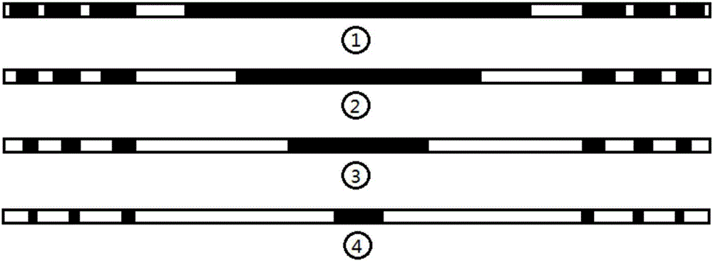
[0026] In the first step, according to the chip size of the ultraviolet detector, determine the size and focal length of the Fresnel lens, design the layout and determine the etching depth.

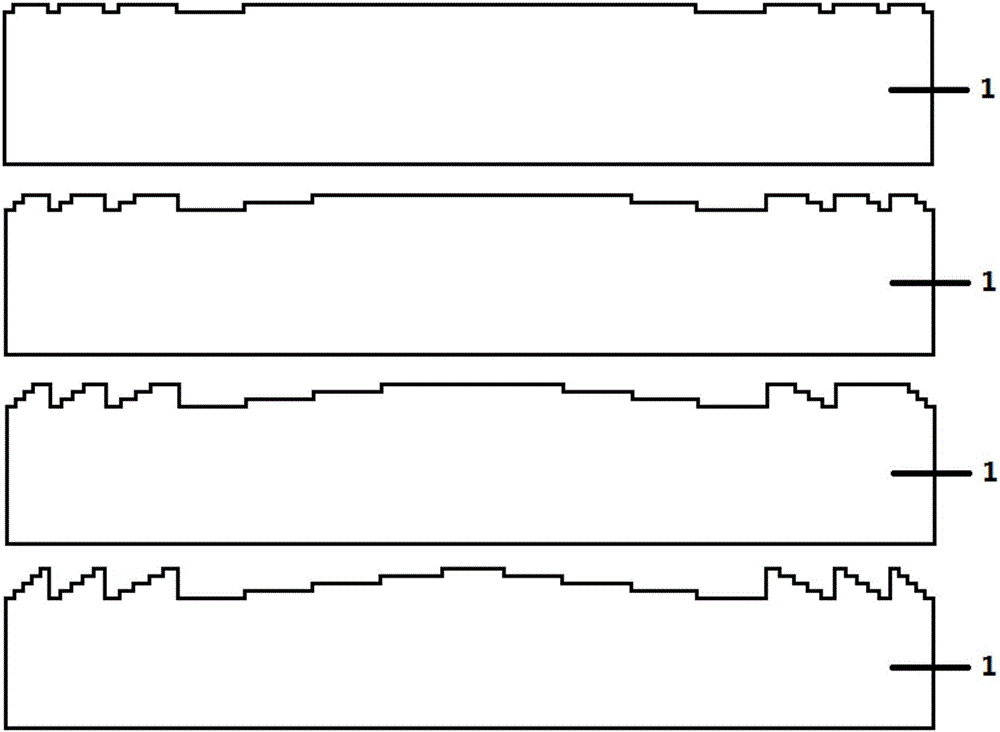
[0027] The second step is to etch a specific pattern on the silicon wafer by using reactive ion etching Si micromachining technology. The four etching depths are equal, each etching is 280nm, and the total step height is 1.12μm, so that UV protection can be achieved. focus function.

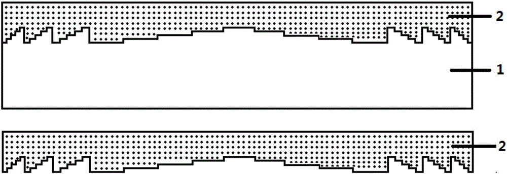
[0028] In the third step, an imprint template is prepared from the above-mentioned silicon wafer with the Fresnel lens structure.

[0029] In the fourth step, after the photoresist is spin-coated on the sapphire window, the above-mentioned imprint template is used for imprinting, and then an etching process is performed to form a sapphire window with a Fresnel lens structure.

[0030] The ultraviolet detectors include but are not limited to: GaN, SiC, ...

Embodiment 2

[0037] This embodiment includes the following steps:

[0038] In the first step, according to the chip size of the ultraviolet detector, determine the size and focal length of the Fresnel lens, design the layout and determine the etching depth.

[0039] In the second step, a specific pattern is etched on the silicon wafer using reactive ion etching Si micromachining technology. focus function.

[0040] In the third step, an imprint template is prepared from the above-mentioned silicon wafer with the Fresnel lens structure.

[0041] In the fourth step, after the photoresist is spin-coated on the sapphire window, the above-mentioned imprint template is used for imprinting, and then an etching process is performed to form a sapphire window with a Fresnel lens structure.

[0042] The ultraviolet detectors include but are not limited to: GaN, SiC, Al x Ga 1-x N, CdS, ZnO, diamond and other UV detectors.

[0043] In the process of dry etching a silicon wafer with a four-layer m...

Embodiment 3

[0049] This embodiment includes the following steps:

[0050] In the first step, according to the chip size of the ultraviolet detector, determine the size and focal length of the Fresnel lens, design the layout and determine the etching depth.

[0051] In the second step, a specific pattern is etched on the silicon wafer using the reactive ion etching Si micromachining process. The depth of the four etchings is equal, each etching is 400nm, and the total step height is 1.6μm, so that the UV radiation can be realized. focus function.

[0052] In the third step, an imprint template is prepared from the above-mentioned silicon wafer with the Fresnel lens structure.

[0053] In the fourth step, after the photoresist is spin-coated on the sapphire window, the above-mentioned imprint template is used for imprinting, and then an etching process is performed to form a sapphire window with a Fresnel lens structure.

[0054] The ultraviolet detectors include but are not limited to: G...


PUM


Abstract

The invention provides a method for producing a fresnel lens on a sapphire window. According to the method, a silicon wafer is firstly designed by a binary optical principle to etch a mask; accurate nested etching is carried out on the surface of the silicon wafer to form a fresnel lens structure; an imprinted template is produced through the etched silicon wafer; and the fresnel lens is produced on the sapphire window through an imprint method and an etching process. Good transmittance of the sapphire window to ultraviolet rays is utilized; and the produced fresnel lens can effectively focus the ultraviolet rays in an ultraviolet ray absorption region of an ultraviolet detector, so that the detection range of the ultraviolet detector is increased; and the sensitivity is improved.

Description

technical field [0001] The invention relates to a technology in the field of optical elements, in particular to a method for preparing a Fresnel lens on a sapphire window and its application. Background technique [0002] Ultraviolet detection technology is widely used in civil and military fields. In the civilian field, ultraviolet detection technology can be applied to such as flame detection, offshore oil monitoring, biomedical analysis, ozone monitoring, solar illumination monitoring, public safety reconnaissance, power equipment detection, etc.; in the military field, ultraviolet detection technology can be applied It is used in early warning guidance and ultraviolet communication of missiles. In short, ultraviolet detection technology is a new photoelectric detection technology for both military and civilian use after infrared and laser detection technology. [0003] Wide-bandgap semiconductors represented by silicon carbide (SiC) and group III nitrides are new third...

Claims


Application Information

Patent Timeline
IPC IPC(8): H01L21/3065H01L21/02G02B3/08
CPCG02B3/08H01L21/02656H01L21/3065
Inventor 袁永刚王建忠刘伯路李政涛张璐璐
Owner 袁永刚
Why Eureka
Try Eureka