Supercharge Your Innovation With Domain-Expert AI Agents!

Furnace tube, wafer cooling method and automatic crystal boat cleaning method

A cooling method and technology for furnace tubes, applied in the fields of furnace tubes, automatic crystal boat cleaning, and wafer cooling, can solve problems such as cumbersome operations and increased machine downtime

Active Publication Date: 2016-07-06
SHANGHAI HUALI MICROELECTRONICS CORP
View PDF3 Cites 2 Cited by
  • Summary
  • Abstract
  • Description
  • Claims
  • Application Information

AI Technical Summary

Problems solved by technology

Such an operation is quite cumbersome and greatly increases the downtime of the machine

Method used


Image

  • Furnace tube, wafer cooling method and automatic crystal boat cleaning method
  • Furnace tube, wafer cooling method and automatic crystal boat cleaning method
  • Furnace tube, wafer cooling method and automatic crystal boat cleaning method

Examples


Embodiment Construction

[0020] In order to make the content of the present invention clearer and easier to understand, the content of the present invention will be described in detail below in conjunction with specific embodiments and accompanying drawings.

[0021] The first preferred embodiment of the present invention designs a brand-new structure of the furnace tube machine, and achieves the purpose of accelerating the cooling speed of the wafer and automatically cleaning the crystal boat by installing a special blowing device at the furnace tube mouth.

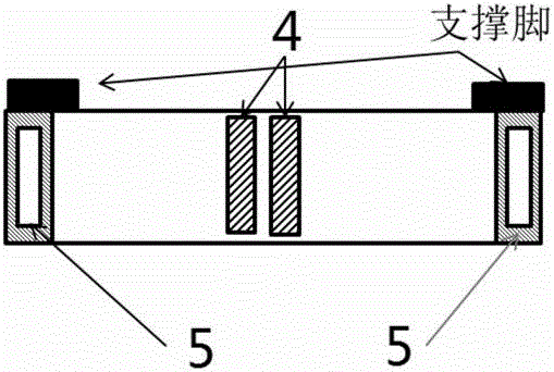
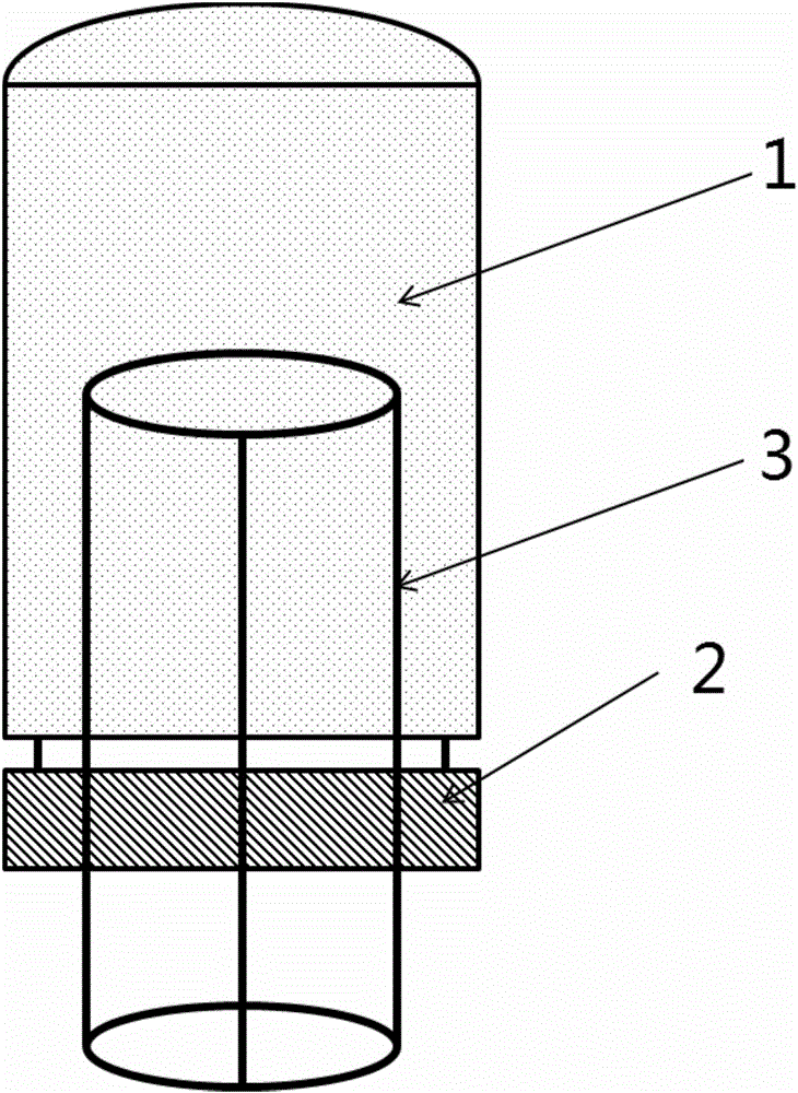
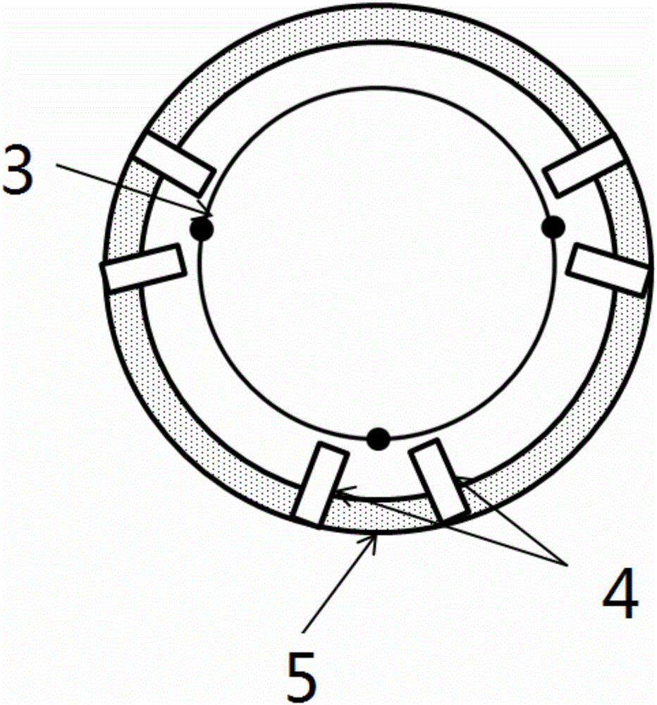
[0022] figure 1 Schematically shows the general structural view of the furnace tube according to the preferred embodiment of the present invention. figure 2 A transverse cross-sectional view of a furnace tube according to a preferred embodiment of the present invention is schematically shown. image 3 A longitudinal section of a furnace tube according to a preferred embodiment of the present invention is schematically shown.

[0023] Such as ...


PUM


Abstract

The invention provides a furnace tube, a wafer cooling method and an automatic crystal boat cleaning method. The furnace tube comprises a furnace tube reaction cavity and a blowing radiator, wherein the blowing radiator is arranged at an opening, for a crystal boat to come in and go out, of the furnace tube reaction cavity; the blowing radiator comprises an annular micropore tube and a plurality of quartz nozzles; the quartz nozzles are arranged on the annular micropore tube for spraying a gas and / or liquid inwards; and the crystal boat passes through the annular micropore tube and the opening and enters the inside of the furnace tube reaction cavity.

Description

technical field [0001] The invention relates to the field of semiconductor manufacturing, more specifically, the invention relates to a furnace tube, a wafer cooling method and an automatic crystal boat cleaning method. Background technique [0002] The cooling speed of traditional furnace tubes is relatively slow, generally requiring more than about 40 minutes of cooling time. The general process time is about 6 hours, and the cooling time accounts for 11% of it. The main reason is that the traditional cooling method relies on the fan installed on the side of the machine to cool the wafers on the boat. Although the air output of the fan is not small, because the fan is installed far away from the wafer boat, it cannot directly blow the wafer boat, and can only cool the wafer by cooling the environment, so it takes a long time. Thereby affecting the operation efficiency of machine platform. [0003] In addition, traditional furnace tubes generally rely on the slots on the...

Claims


Application Information

Patent Timeline
Patent Type & Authority Applications(China)
IPC IPC(8): H01L21/67H01L21/673F27D9/00B08B3/02
CPCB08B3/02F27D9/00H01L21/67H01L21/673
Inventor 张乐成张召王智苏俊铭
Owner SHANGHAI HUALI MICROELECTRONICS CORP
Features
  • R&D
  • Intellectual Property
  • Life Sciences
  • Materials
  • Tech Scout
  • Unparalleled Data Quality
  • Higher Quality Content
  • 60% Fewer Hallucinations
Learn More