Electron stopping device

A stopping device and electronic technology, applied in circuit devices, battery circuit devices, electric vehicles, etc., can solve the problems of inability to recover energy, low efficiency of the energy recovery system, and difficulty in controlling the stopping process of the braking device, and achieve excellent output characteristics. Effect

Active Publication Date: 2016-07-06
陈正有
View PDF4 Cites 0 Cited by
  • Summary
  • Abstract
  • Description
  • Claims
  • Application Information

AI Technical Summary

Problems solved by technology

[0003] The present invention mainly solves the technical problems existing in the prior art that the stopping process of the braking device is difficult to control and cannot recover e

Method used


Image

  • Electron stopping device
  • Electron stopping device
  • Electron stopping device

Examples


Embodiment

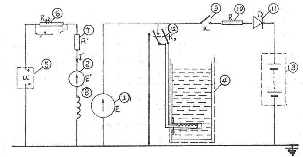
[0029] Embodiment: a kind of electronic stopping device of this embodiment, such as figure 1 As shown, it is mainly composed of: main generator 1, compensation machine 2, energy storage battery pack 3, hot water storage tank 4 and other parts. The main generator is a separately excited DC generator, its function is to convert the remaining kinetic energy of the car into electrical energy, and store the electrical energy in the battery pack by charging the battery pack. The excitation circuit of the main generator consists of excitation power supply u′(5), correction resistor R 校 (6) Consists of current limiting resistor R'7, compensation machine and excitation winding 8 of the main generator, wherein the compensation machine is opposite in polarity to the excitation power supply u'. The output circuit of the main generator is composed of two branch circuits connected in parallel, one branch is switch K1(9), current limiting resistor R(10), isolation diode D(11) and energy sto...


PUM


Abstract

The invention discloses an electron stopping device, which comprises a main generator, an exciter circuit and an output circuit, wherein the main generator is a separate-excitation DC generator; the exciter circuit comprises an excitation power supply, a correction resistor, a current-limiting resistor R', a compensation machine, a speed control relay and an exciting winding of the main generator; the excitation power supply, the correction resistor, the current-limiting resistor R', the compensation machine, the speed control relay and the exciting winding are sequentially connected in series to form a loop; the compensation machine and the excitation power supply are opposite in polarity; a contact group of the speed control relay controls the correction resistor and the compensation machine; an output end of the main generator is connected with the output circuit; and an input shaft of the main generator, the input shaft of the compensation machine and the input shaft of an AC generator in the speed control relay are driven by a drive shaft of an external power source. According to the electron stopping device, an exciting current of the main generator is changed through the compensation machine to prompt a great change of the output characteristic of the main generator; in the whole stopping process, the output electromotive force of the main generator can still be kept constant basically under the condition of monotonic decreasing of the vehicle speed; and the electron stopping device has relatively high energy conversion efficiency and relatively high output power.

Description

technical field [0001] The invention relates to the fields of electrical technology, electronic technology and the like, in particular to an electronic stop device. Background technique [0002] The essence of stopping is to convert all the kinetic energy of the object into other forms of energy. Generally speaking, the process of this energy conversion is the process that the moving object overcomes the external force to do work, and the performance of the stopper is determined by the actual situation of this work process. The common stopping device in reality is called "brake", which uses objects to overcome friction and do work to convert all kinetic energy into heat energy to achieve the purpose of stopping. The simple structure and obvious stop effect are the reasons why the "brake" device lasts for a long time. However, "brakes" also have many defects, such as worn-out machinery and the converted kinetic energy cannot be recycled again, especially the hard-to-control...

Claims


Application Information

Patent Timeline
IPC IPC(8): H02P9/14H02J7/14
CPCH02J7/14H02P9/14
Inventor 陈正有
Owner 陈正有
Why Eureka
Try Eureka