Fluid static mixing device with corrugated pipeline

A static mixing device and wave-shaped technology, which is applied in the direction of fluid mixers, mixers, cement mixing devices, etc., can solve the problems of not too high flow rate of mixed fluid, large difference in density of mixed fluid, etc., to achieve improved mixing capacity, Increased flow rate and strong mixing ability

Inactive Publication Date: 2016-07-13
NANYANG NORMAL UNIV
View PDF2 Cites 6 Cited by
  • Summary
  • Abstract
  • Description
  • Claims
  • Application Information

AI Technical Summary

Problems solved by technology

However, this patent can only be applied to the situation where the density difference of the mixed fluid is large and the flow rate of the mixed fluid is not too high

Method used


Image

  • Fluid static mixing device with corrugated pipeline
  • Fluid static mixing device with corrugated pipeline
  • Fluid static mixing device with corrugated pipeline

Examples


Embodiment 1

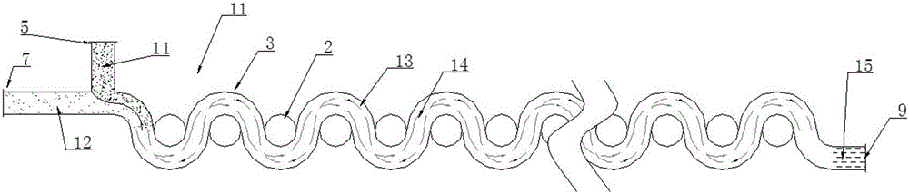
[0061] Application of the present invention on pesticide dilution, mixing, spraying, such as Image 6 shown.

[0062] The current pesticide spraying machines have to mix and dilute the pesticides through manual or mechanical exposure before spraying, which undoubtedly poses a certain threat to the safety of the environment and operators. And use the present invention just can solve this problem well.

[0063] 1. Production and connection of equipment

[0064] (1) Production of equipment

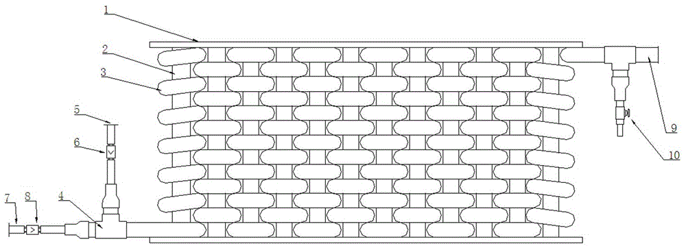
[0065] For the majority of farmers, such as figure 1 The shown structure makes the device (flexible pipe) of the present invention with a bending radius greater than the outer diameter of the pipe. In order to ensure that various pesticides can be mixed evenly, the number of semicircular pipes can be appropriately more, generally greater than 12.

[0066] (2) Device connection

[0067] Choose a small plunger pump and a peristaltic pump whose flow rate can be adjusted by rotating speed, p...

Embodiment 2

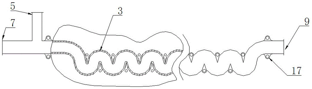
[0072] Application of the present invention on foam preparation, such as Figure 7 Shown, flexible pipe.

[0073] The current blowing agent dilution mixing device such as Figure 9 As shown, it only relies on the vortex formed by water at the end of the "U" tube to mix with the foaming agent stock solution, which is not effective and affects the foam quality, especially for foaming agents with high viscosity. The present invention can be applied to liquid foaming agents with different viscosities. Even for solid powder foaming agents, the input device can be uniformly diluted and mixed, thereby improving foam quality.

[0074] 1. Production and connection of equipment

[0075] The design foaming energy capacity of present embodiment foaming machine is 18m 3 / h foam, so choose a plunger pump with an outlet pressure of 0.6MPa and a flow rate of 6.5kg / min, a peristaltic pump with a maximum flow rate of 0.4kg / min that can be adjusted by rotating speed, and a 3m-long inner diame...

Embodiment 3

[0083] Application of the present invention in the preparation of foamed concrete, such as Figure 10 As shown, rigid pipe.

[0084] 1. Production and connection of equipment

[0085] The design capacity of the foaming machine of the present embodiment is 18m 3 / h foam (same as Example 2), it is 300kg / m 3 The production capacity of foam concrete is 20m 3 / h, so choose one with a maximum flow rate of 3.5m3 / h, a maximum speed of 52rpm, an outlet pressure ≤0.8Mpa, a suction lift of not less than 9m, a hose inner diameter of 40mm, a power supply voltage of 380V, 50Hz, and a power of 4kW. Hose pumps (aka peristaltic pumps). The speed of the hose pump is regulated by a frequency converter.

[0086] Such as Figure 10 As shown, the mixing device of the foam and concrete slurry of this embodiment is formed. In the device, the manufacturing method of the present invention is as follows.

[0087] 1. First use the φ40 flexible pipe to conduct experiments, and determine that the n...


PUM

PropertyMeasurementUnit
densityaaaaaaaaaa
densityaaaaaaaaaa

Abstract

The invention discloses a fluid static mixing device with a corrugated pipeline.The device comprises the mixing pipeline, a main material inlet pipe, an auxiliary material inlet pipe and a mixed material outlet pipe, wherein the main material inlet pipe and the auxiliary material inlet pipe are arranged at one end of the mixed pipeline, the mixed material outlet pipe is arranged at the other end of the mixed pipeline, and the mixed pipeline is a corrugated pipe body.By means of the corrugated pipeline, fluids which have different densities and conduct one-way movement are automatically mixed in the corrugated pipeline, and the mixing capacity is high, an appropriate number of semicircular pipelines and the flow velocity of the mixed fluid can be set according to the mixed objects and aims and demands.By means of the fluid static mixing device with the corrugated pipeline, the flow velocity is increased, and the mixing capacity, produced from centrifugal force, of the fluids with different densities can be improved and exceeds the gravity finally or even is improved in multiples.

Description

technical field [0001] The invention belongs to the field of chemical machinery, and in particular relates to a fluid static mixing device with a wave-shaped pipeline. Background technique [0002] Liquid-liquid, gas-gas and gas-liquid mixing are frequently encountered problems in many fields such as chemical production and daily life. At present, the mixing equipment developed by people can be roughly divided into two types: dynamic and static. Dynamic mixing equipment is generally equipped with stirring blades, and some are also equipped with stationary blades that are staggered or staggered with the stirring blades. Static mixing equipment is mostly pipeline type, which can be divided into variable diameter type and equal diameter type. Most of them are equipped with fixed blades in different directions in the pipe, and the mixing of two or several fluids is realized by means of the transmission power of the mixed fluid. Compared with the above-mentioned mixing equipmen...

Claims


Application Information

Patent Timeline
Patent Type & Authority Applications(China)
IPC IPC(8): B01F5/06B28C5/06
CPCB28C5/06B01F25/4332B01F25/4331
Inventor 王利亚李森兰赵洁李雄文郭楠
Owner NANYANG NORMAL UNIV
Why Eureka
Try Eureka