
Spiral coil and plunger combined type injection molding device

An injection molding device and combined technology, which is applied in the field of injection molding of polymer materials, can solve the problems of screw plasticization, crushing and extrusion capabilities, high complexity of the overall system, and high cost, and achieve the inherent quality and Improved appearance quality, optimized processing process, and strong plasticizing ability

Active Publication Date: 2016-07-13
ANHUI YINUOQINGCHUN IND DESIGN CO LTD
View PDF2 Cites 2 Cited by
  • Summary
  • Abstract
  • Description
  • Claims
  • Application Information

AI Technical Summary

Problems solved by technology

[0006] In the traditional reciprocating screw injection molding machine, the screw has two functions of plasticizing and injecting at the same time. The screw performs rotary motion to plasticize the material, and at the same time performs reciprocating axial motion to inject, so the complexity of the overall system is high. The cost is high, and during plasticization, along with the axial movement of the screw, the melt forms an insurmountable axial temperature difference
[0007] The traditional injection machine also has a common feature, that is, the screw is generally used to plasticize the material. Although the plasticization of the screw has its advantages, for some materials, the screw has the disadvantages of plasticizing, crushing and extrusion.
[0008] In view of the problems existing in traditional injection machines, although many researchers have explored, they are only limited to local changes to the screw or plunger, without changing the fundamental reason for the existence of the above-mentioned overall system

Method used


Image

  • Spiral coil and plunger combined type injection molding device
  • Spiral coil and plunger combined type injection molding device
  • Spiral coil and plunger combined type injection molding device

Examples


Embodiment 1

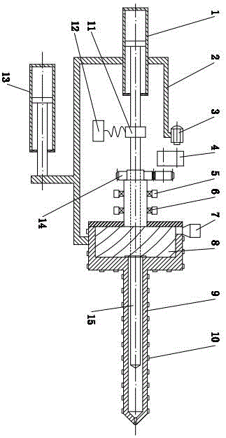
[0036] Such as Figure 1 to Figure 4 As shown, it is a combined screw and plunger injection molding device, including injection cylinder 1, injection seat frame 2, motor 3, transmission mechanism 4, seat 5, centripetal thrust bearing 6, hopper 7, barrel 9. Electric heater 10, mobile cylinder 13, gear 14 and plunger 15;

[0037] The injection cylinder 1, the motor 3 and the transmission mechanism 4 are all installed on the injection seat frame 2, and the push rod of the mobile oil cylinder 13 is connected with the injection seat frame 2, so that the push rod of the mobile oil cylinder 13 can push the injection seat frame 2 to move ;

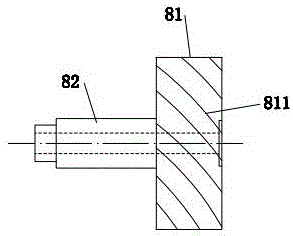
[0038] Described plasticizing screw disk 8 comprises rotating disk 81 and cylinder 82, and described cylinder 82 is positioned at the left end of rotating disk 81, and is provided with more than three outer circumferential screw grooves 811 on the cylindrical surface of described rotating disk 81, on the rotating disk 81 The right end face is pr...

Embodiment 2

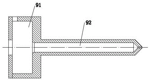
[0044] Such as Figure 5 As shown, it is a combination screw and plunger injection molding device, its structure and working principle are basically the same as the first embodiment, the difference is that the injection cylinder 92 is a stepped hole, and the stepped hole The part with a large middle diameter is connected to the plasticizing chamber 91, and the part with a small diameter in the stepped hole is connected with the injection hole. Good melt material can enter the right section of the injection cylinder 92 through this gap under pressure, and the outer circular surface of the right part of the plunger 15 is in a sliding fit with the part of the stepped hole of the injection cylinder 92 with a small diameter, but the melt material cannot be fitted from it. Pass through the gap, but the volume of the small hole in the stepped hole must be greater than the minimum injection volume set by the injection machine. The working principle is basically the same as that of Em...

Embodiment 3

[0046] Such as Figure 6 As shown, it is a combined screw and plunger injection molding device. Its structure and working principle are basically the same as those in Embodiment 1. Reverse head 16 ), the one-way valve 16 (or non-return head 16 ) is located in the injection cylinder 92 , and the one-way valve 16 (or non-return head 16 ) can move axially in the injection cylinder 92 . The non-return head is a device to prevent the molten material from flowing back during injection. Its working principle is very similar to that of a one-way valve. Since this technology is relatively mature and is not the focus of this patent, the structure of the non-return head will not be discussed here. The principle is described.

[0047] When working, the motor 3 drives the plasticizing screw disk 8 to rotate through the transmission mechanism 4 and the gear 14. The outer circumferential thread groove 811 and the end surface spiral groove 812 on the plasticizing screw disk 8 are used as mat...


PUM


Abstract

The invention relates to a spiral coil and plunger combined type injection molding device.The device comprises an injection oil cylinder, an injection seat frame, a motor, a transmission mechanism, a base, an angular-contact bearing, a hopper, a cylinder, an electric heater, a movable oil cylinder, a gear and a plunger.The device is characterized by further comprising a plasticized spiral coil, the plasticized spiral coil comprises a turnplate and a cylindrical body, three or more external circumference screw channels are formed in the cylindrical surface of the turnplate, three or more end face screw channels are formed in the right end face of the turnplate, and the right end of each external circumference screw channel is communicated with the corresponding end face screw channel; center holes are formed in the turnplate and the cylindrical body; the cylinder comprises a cylindrical plasticization chamber and an injection cylinder, the turnplate is located in the plasticization chamber and can rotate, the hopper is installed on the plasticization chamber, the left end of each external circumference screw channel is communicated with the hopper through a radial hole, and each end face screw channel is communicated with the right end of the corresponding external circumference screw channel and the left end of the injection cylinder; the plunger is in clearance fit with the injection cylinder.The device has the advantages that structure is simple and compact, a charging barrel is convenient to clean, plasticizing capacity, smashing capacity and extruding capacity are high, and the quality of products is high.

Description

technical field [0001] The invention relates to a combined screw disk and plunger injection molding device, which is mainly used for plasticizing and injection molding polymer materials, and belongs to the technical field of polymer material injection molding. Background technique [0002] Plastic injection molding has the advantages of simple process, high production efficiency, and accurate product size, and can mold products with complex shapes in a short period of time. [0003] The plasticizing injection device is one of the core structures of injection molding equipment. Its performance not only directly affects the efficiency of injection molding, production cost and production environment, but also has a decisive impact on the quality of injection products. [0004] There are two kinds of the most common plasticizing injection devices at present, one is the screw plunger type, and the other is the reciprocating screw type. [0005] The traditional screw plunger inje...

Claims


Application Information

Patent Timeline
IPC IPC(8): B29C45/53B29C45/58B29C45/62
CPCB29C45/531B29C45/585B29C45/62
Inventor 陈学锋凃明霞徐言生胡建国柯美元曾宪荣
Owner ANHUI YINUOQINGCHUN IND DESIGN CO LTD
Features
  • Generate Ideas
  • Intellectual Property
  • Life Sciences
  • Materials
  • Tech Scout
  • Unparalleled Data Quality
  • Higher Quality Content
  • 60% Fewer Hallucinations
Learn More