Injection molding device with spherical rotor

An injection molding device and spherical rotor technology, applied in the field of injection molding devices, can solve the problems of inconvenient barrel cleaning, large axial temperature difference, screw plasticization, crushing and extrusion capabilities, etc., and achieve simple and reliable structure, extrusion strong pressure effect

Active Publication Date: 2016-07-13
泗县微腾知识产权运营有限公司
View PDF2 Cites 5 Cited by
  • Summary
  • Abstract
  • Description
  • Claims
  • Application Information

AI Technical Summary

Problems solved by technology

The problem with this method is that there are often many stagnant materials in the barrel, which is not easy to clean the barrel. Since two sets of barrels are required (one set for plasticization and one set for injection), the volume of the machine and the number of parts are increased. Not only the manufacturing cost is high, but also two sets of heating systems are required to heat the screw plasticizing system and the plunger injection system respectively, which increases the overall energy consumption
[0004] The traditional reciprocating screw injection molding machine cancels the injection plunger, and the screw has two functions of plasticization and injection at the same time, so the screw not only needs to rotate to complete the plasticization of the material, but also needs to do reciprocating axial movement Injection, which greatly increases the complexity and difficulty of the overall system, increases the cost of manufacturing, use and maintenance, and, during plasticization, due to the axial movement of the screw, the temperature difference in the axial direction formed by the melt temperature is relatively large , and difficult to overcome
[0005] Another feature of the traditional injection machine is that the screw is generally used to plasticize the material. Although the plasticization of the screw has its advantages, for some materials, the screw has the disadvantages of plasticizing, crushing and extrusion.
[0006] In view of the problems existing in traditional injection machines, although many researchers have explored, they are all limited to local changes to the screw, plunger, control system or other components, and have not changed the fundamental problems of the above-mentioned overall system. Therefore, , must be changed from the overall structure and the principle of action, in order to get the overall and fundamental perfection

Method used


Image

  • Injection molding device with spherical rotor
  • Injection molding device with spherical rotor
  • Injection molding device with spherical rotor

Examples


Embodiment 1

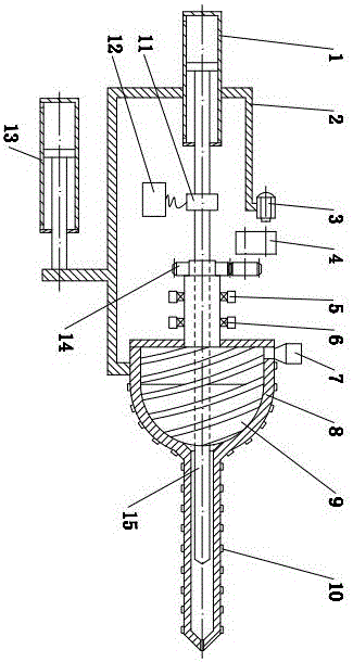
[0032] Such as Figure 1 to Figure 3 As shown, it is an injection molding device with a spherical rotor, including an injection cylinder 1, an injection seat frame 2, a motor 3, a transmission mechanism 4, a seat 5, a centripetal thrust bearing 6, a hopper 7, a barrel 8, a plastic Chemical rotor 9, electric heater 10, vibrating device 11, motion controller 12, mobile oil cylinder 13, gear 14 and plunger 15;

[0033] The injection cylinder 1 , motor 3 , transmission mechanism 4 and barrel 8 are fixed on the injection seat frame 2 .

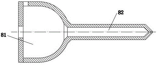
[0034] The barrel 8 includes a hemispherical plasticizing cavity 81 and an injection cylinder 82, and the hopper 7 is installed on the plasticizing cavity 81 of the barrel 8;

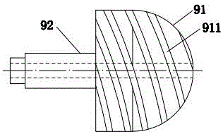
[0035] Described plasticizing rotor 9 comprises hemispherical rotor 91 and the cylindrical body 92 that is integrated with hemispherical rotor 91, is provided with continuous external screw groove 911 on described hemispherical rotor 91, and hemispherical rotor 91 and cylin...

Embodiment 2

[0043] Such as Figure 4 As shown, it is an injection molding device with a spherical rotor. Its basic mechanism principle is basically the same as that of Embodiment 1. The difference is that the inner hole of the injection cylinder 82 is a stepped hole, and the part with a large diameter in the stepped hole is related to the plasticizing Cavity 81 is connected, and the part of the small hole in the stepped hole is connected with the injection hole. There is a certain gap between the outer circular surface of the right part of the plunger 15 and the section with a large hole in the stepped hole, and the plasticized melt can be injected under pressure. Enter the right section of the injection cylinder 82 through this gap, and the outer circular surface of the right part of the plunger 15 is in a sliding fit with the part with a small diameter in the stepped hole, but the molten material cannot pass through the fitting gap, and the part with a small diameter in the stepped hole ...

Embodiment 3

[0045] Such as Figure 5 As shown, it is an injection molding device with a spherical rotor. Its structure and working principle are basically the same as those in Embodiment 1. The reverse head 16 , the one-way valve or the check head 16 is located in the injection cylinder 82 , and the one-way valve or the check head 11 can move axially in the injection cylinder 82 .

[0046] When working, the motor 3 drives the hemispherical rotor 91 to rotate through the transmission mechanism 4 and the gear 14. The external thread groove 911 on the hemispherical rotor 91 and the plasticizing cavity 81 of the machine barrel 8 form a material plasticizing and transporting channel. The material enters the external thread groove 911 on the outer circumference of the hemispherical rotor 91 through the radial hole of the plasticizing chamber 81 of the barrel 8, moves to the right side along the external thread groove 911 to the right end of the hemispherical rotor 91 and enters the injection ba...


PUM


Abstract

The invention relates to an injection molding device with a spherical rotor.The injection molding device comprises an injection oil cylinder, an injection seat frame, a motor, a transmission mechanism, a stand, an angular-contact bearing, a hopper, a machine barrel, an electric heater, a movable oil cylinder, a gear and a plunger.The injection molding device is characterized by further comprising the plasticizing rotor which comprises a hemispherical rotor body and a cylinder connected with the hemispherical rotor body into a whole, and a continuous outer threaded groove is formed in the hemispherical rotor body; the machine barrel comprises a hemispherical plasticizing cavity and an injection barrel, the hemispherical rotor body is located in the hemispherical plasticizing cavity and can rotate, the hopper is installed in the plasticizing cavity, the left end of the outer threaded groove is communicated with the hopper, and the right end of the outer threaded groove is communicated with the injection barrel; the plunger is located on the hemispherical rotor body and in a central hole of the cylinder and the injection barrel and can axially move, a vibrating device is installed between the plunger and a push rod of the injection oil cylinder, and the plunger is in clearance fit with the injection barrel.The injection molding device has the advantages of being high in plasticizing, smashing and squeezing capability, good in molded product quality and the like.

Description

technical field [0001] The invention relates to an injection molding device with a spherical rotor, which is mainly used for plasticizing and injection molding polymer materials, and belongs to the technical field of injection molding equipment for materials and polymer materials. Background technique [0002] Plastic injection molding has the advantages of simple process, high production efficiency, and accurate product size, and can mold products with complex shapes in a short period of time. The plasticizing injection device is one of the core structures of injection molding equipment. Its performance not only directly affects the efficiency of injection molding, production cost and production environment, but also has a decisive impact on the quality of injection products. [0003] The traditional screw plunger injection molding machine adds a set of single-screw extrusion feeding device only for plasticization to the plunger injection device. The material needs to be pl...

Claims


Application Information

Patent Timeline
Patent Type & Authority Applications(China)
IPC IPC(8): B29C45/54B29C45/60B29C45/58
CPCB29C45/541B29C45/585B29C45/586B29C45/60B29C2045/547B29C45/53B29C45/54B29C45/62B29C2045/1794
Inventor 陈学锋凃明霞徐言生胡建国柯美元曾宪荣
Owner 泗县微腾知识产权运营有限公司
Why Eureka
Try Eureka