
A semi-active control method for an energy-feeding semi-active suspension system

A semi-active control and semi-active suspension technology, applied in the direction of suspension, elastic suspension, circuit or fluid pipeline, etc., can solve the problem of less design, and achieve the expansion of bandwidth, reduction of dynamic error, and reduction of dynamic and stability. The effect of state error

Active Publication Date: 2018-11-09
JIANGSU UNIV
View PDF5 Cites 2 Cited by
  • Summary
  • Abstract
  • Description
  • Claims
  • Application Information

AI Technical Summary

Problems solved by technology

The research on the energy-fed suspension mostly focuses on the analysis of the dynamic performance of the suspension system and the design of the overall structure of the suspension, and there are relatively few designs on the suspension hardware control circuit and the controller for the control circuit.

Method used


Image

  • A semi-active control method for an energy-feeding semi-active suspension system
  • A semi-active control method for an energy-feeding semi-active suspension system
  • A semi-active control method for an energy-feeding semi-active suspension system

Examples


Embodiment Construction

[0032] The semi-active control method of the energy-feeding semi-active suspension system of the present invention will be described in more detail below in conjunction with the accompanying drawings:

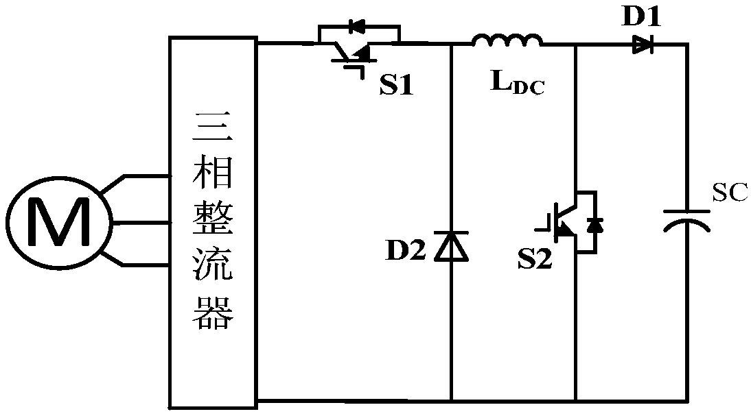
[0033] Such as figure 1 As shown, a semi-active control method of an energy-feeding semi-active suspension system of the present invention, the schematic diagram of the semi-active control loop includes: a linear motor M, a three-phase rectifier, a MOS tube S1, a MOS tube S2, Diode D1, Diode D2, Inductor L DC , supercapacitor bank SC. The output end of the linear motor M is connected to the input end of the three-phase rectifier, the anode of the two-phase output end of the three-phase rectifier is connected to the drain of the MOS transistor S1, and the source of the MOS transistor S1 is connected to the diode D2 at the same time. Negative pole and inductance L DC connected to one end of the inductor L DC The other end of the MOS transistor S2 is connected to the drain of ...


PUM


Abstract

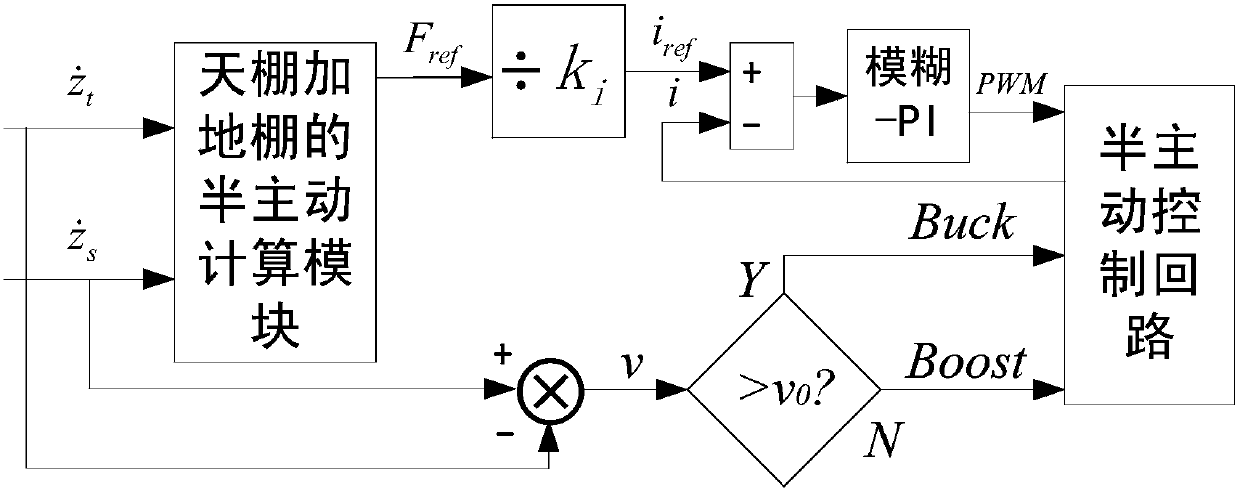
The invention discloses a semi-active control method of an energy reclaiming type semi-active suspension system. The semi-active control method is characterized by obtaining an ideal electromagnetic damping force Fref required to be output by a linear motor through a skyhook and groudhook suspension damping semi-active control strategy; dividing the ideal electromagnetic damping force Fref by an electromagnetic damping coefficient ki, thus obtaining a needed reference current iref; collecting a real current value ireal in a motor winding through a current sensor; inputting a difference value e of the reference current iref and the real current value ireal and a difference value change rate ec into a fuzzy-PI (Proportion Integration) mixed controller; outputting two paths of pulse signals by the fuzzy-PI mixed controller to control the switching on and off of an MOS (Metal Oxide Semiconductor) transistor in a semi-active control circuit, thus realizing semi-active control.

Description

technical field [0001] The invention relates to the field of energy recovery of automobiles, more precisely to the field of vibration energy recovery of an energy-feeding semi-active suspension. Background technique [0002] With the aggravation of energy crisis and environmental pollution, how to reduce the energy consumption of the vehicle body has attracted the attention of all walks of life. The energy-feeding semi-active suspension can recover the vibration energy of the vehicle body and reduce the fuel consumption of the vehicle body. The research on the energy-fed suspension is mostly aimed at the analysis of the dynamic performance of the suspension system and the design of the overall structure of the suspension, and there are relatively few studies on the suspension hardware control circuit and the controller for the control circuit. Contents of the invention [0003] The semi-active control method of an energy-feeding semi-active suspension system disclosed by ...

Claims


Application Information

Patent Timeline
Patent Type & Authority Patents(China)
IPC IPC(8): B60G17/015B60R16/023B60R16/037
CPCB60G17/0157B60G17/019B60G17/01933B60G2200/00B60G2400/20B60G2600/184B60R16/0231B60R16/037
Inventor 汪若尘丁彦姝钱金刚丁仁凯陈龙
Owner JIANGSU UNIV
Learn More