
Anti-lock braking device of steering drive axle hub brake and design method thereof

An anti-lock braking, braking technology, applied in the direction of brakes, ABS control systems, etc., to achieve the effect of widening the width and avoiding interference

Inactive Publication Date: 2016-07-13
福建省晋江市东石肖下连盛机械配件厂(普通合伙)
View PDF7 Cites 11 Cited by
  • Summary
  • Abstract
  • Description
  • Claims
  • Application Information

AI Technical Summary

Problems solved by technology

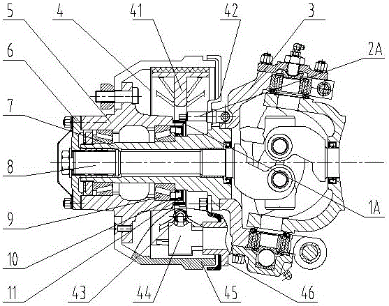
[0004] However, if the ABS anti-lock braking system is installed on the steering drive front axle with hub brakes, the steering knuckle shell, brake assembly, outer half shaft, wheel hub, hub shaft tube, cone bearing, Oil seals and other parts, the ribs on the brake shoe of the brake assembly and the position of the return spring limit the large diameter of the ring gear rotor, while the size of the tapered bearing and oil seal limit the small diameter of the ring gear rotor, the brake bottom plate and the brake shoe The distance is very small, which limits the axial position of the ring gear rotor and the wheel speed sensor; if the wheel speed sensor is placed in the steering knuckle housing, it will interfere with the rotating outer half shaft

Method used


Image

  • Anti-lock braking device of steering drive axle hub brake and design method thereof
  • Anti-lock braking device of steering drive axle hub brake and design method thereof
  • Anti-lock braking device of steering drive axle hub brake and design method thereof

Examples


Embodiment Construction

[0032] Best practice:

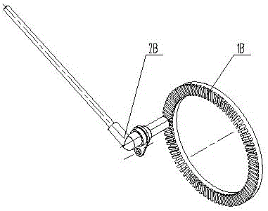
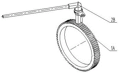
[0033] Refer to attached image 3 , the anti-lock braking device of the steering drive axle hub brake brake, including cylindrical tooth rotor 1A, flat head wheel speed sensor 2A, steering knuckle shell 3, brake assembly 4, hub 5, outer half shaft flange 6, hub shaft Pipe 7, outer half shaft 8, taper bearing 9, spacer sleeve 10, oil seal 11, etc. Brake assembly 4 is made up of brake shoe and friction plate assembly 41, brake base plate 42, return spring 43, camshaft 44, brake hub 45, camshaft support 46, adjustment arm, push rod and air chamber etc.

[0034] The design method of the anti-lock braking device of the above-mentioned steering drive axle hub brake is as follows:

[0035] First, the radial space required for the spur tooth rotor 1A is set. The inner hole of the cylindrical tooth rotor 1A and the outer diameter of the hub 5 adopt an interference fit, and are press-fitted on the hub 5 . This requires the oil seal 11 and the spacer 10 with t...


PUM


Abstract

The invention relates to an automotive anti-lock braking system (ABS) technology, in particular to an anti-lock braking device of a steering drive axle hub brake and an ABS anti-lock braking structure for a steering drive front axle with a hub brake.The anti-lock braking device is structurally characterized by further comprising a gear ring and a wheel speed sensor, the gear ring is a cylindrical gear rotor installed on a peripheral face of one side end, provided with an oil seal and a spacer bush, of a hub, the internal diameter of the cylindrical gear rotor is in interface fit with the external diameter of the hub, and the cylindrical gear rotor is installed on the hub in a pressing mode; the wheel speed sensor is installed on the inner side face of a brake bottom plate and is parallel to the center axis of the hub, the sensing end of the wheel speed sensor is of a flat head structure distributed parallel to a gear crest of the cylindrical gear rotor.The anti-lock braking device has the advantages that the infinite space is fully utilized without affecting the assembly intensity, the steering drive front axle ABS anti-lock braking device is realized; the interval precision of the sensor and the cylindrical gear rotor is accurate and does not need to be adjusted; the flat head wheel speed sensor is more sensitive in sensing.

Description

technical field [0001] The invention relates to an automobile ABS anti-lock braking system technology, in particular to an anti-lock braking device for a steering drive axle hub brake and a design method thereof, in particular to a steering drive front axle with a hub brake Advanced ABS anti-lock braking structure. Background technique [0002] During the braking process of the car, the movement of the wheels on the road is a process of rolling and sliding. When the car is not braked, the wheels are in a pure rolling state; when the wheels are braked and locked, the movement of the wheels on the road is in a pure sliding state. In this state, it will cause accidents such as steering failure and rollover, which is very dangerous. The ABS anti-lock braking system can enable the car to obtain the best braking performance, prevent the wheels from locking and slipping during braking, and control the wheel slip rate within a narrow range near the ideal slip rate. Make the car ma...

Claims


Application Information

Patent Timeline
IPC IPC(8): B60T8/80
CPCB60T8/74B60T2270/10
Inventor 王国良肖益友肖有恒
Owner 福建省晋江市东石肖下连盛机械配件厂(普通合伙)
Learn More