Device and method for degassing optical fiber preform rods
An optical fiber preform and degassing device technology, applied in the field of optical fiber manufacturing, can solve problems such as being unsuitable for large-scale production, and achieve the effects of promoting rod structure adjustment, reducing internal stress, and reducing energy consumption
- Summary
- Abstract
- Description
- Claims
- Application Information
AI Technical Summary
Problems solved by technology
Method used
Image
Examples
Embodiment 1
[0033]Example 1: Using a method similar to a common degassing furnace (comparative example), without using a vacuum pipeline, the pressure in the quartz chamber is 1 atm.
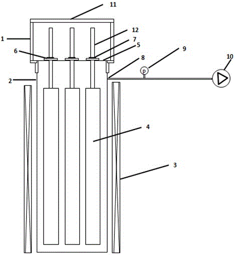
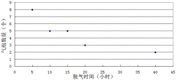
[0034] An optical fiber preform powder rod is produced by VAD technology, and a preform rod with an outer diameter of about 80mm is formed after sintering, and a quartz orifice plate with an aperture of 90mm is selected. A quartz glass sealing gasket with an outer diameter of 100mm is installed on the target rod. Slowly pass the preform through the quartz orifice plate, hang it on the quartz glass orifice plate through the bolt, close the sealing cover, set the heat preservation temperature to 900°C, and enter the heat preservation process. In order to reflect the influence of the holding time, set the holding time as 5h, 10h, 15h, 20h, 40h respectively. After degassing, the prefabricated rod mother rod is stretched into a core rod with an outer diameter of 40mm, and the number of bubbles is analyzed to te...
Embodiment 2
[0036] Embodiment 2: Use the vacuum degassing method proposed in the present invention, set the exhaust pressure, and open the PID loop adjustment.
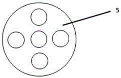
[0037] Five prefabricated rod powder rods are produced by VAD process, and after sintering, a preformed rod with an outer diameter of about 80mm is formed, and a quartz glass orifice plate with an aperture of 90mm is selected. A quartz glass sealing gasket with an outer diameter of 100mm is installed on the target rod. After passing the preform through the orifice plate of quartz glass, hang it on the orifice plate of quartz glass through the bolt, close the sealing cover, set the cavity pressure to 100mbar, and start vacuuming. At the same time, a PID pressure feedback control loop is set on the exhaust pipe to control the exhaust pressure and ensure the pressure is stable. Set the temperature of the holding furnace to 900°C, and then enter the heat preservation process. Take out a preform rod when the holding time is 5h, 10h,...
Embodiment 3
[0039] Embodiment 3: 5 prefabricated powder rods were produced by VAD technology, and after sintering, a preform with an outer diameter of about 120 mm was formed, and a quartz orifice plate with an aperture of 130 mm was selected. A quartz sealing ring with an outer diameter of 140mm is installed on the target rod. After the preform passes through the quartz glass orifice plate, it is suspended on the quartz glass orifice plate through a bolt. Ensure that the holding time is 10h, the annealing temperature is 900°C, adjust the pressure of the exhaust pipe to 10mbar, 30mbar, 60mbar, 150mbar, and 300mbar respectively, and open the PID pressure feedback control loop of the discharge pipe to adjust the pressure to keep the pressure stable.
[0040] After the preform rods undergoing different degassing conditions are stretched into 40mm outer diameter mandrels, they are placed on the detection platform to detect the number of bubbles and give feedback on the degassing effect. from...
PUM
 Abstract
Description
Claims
Application Information
 - R&D
- Intellectual Property
- Life Sciences
- Materials
- Tech Scout
- Unparalleled Data Quality
- Higher Quality Content
- 60% Fewer Hallucinations
Browse by: Latest US Patents, China's latest patents, Technical Efficacy Thesaurus, Application Domain, Technology Topic, Popular Technical Reports.
© 2025 PatSnap. All rights reserved.Legal|Privacy policy|Modern Slavery Act Transparency Statement|Sitemap|About US| Contact US: help@patsnap.com


