Vacuum generator

A technology of vacuum generator and vacuum port, which is applied in the direction of machines/engines, non-volume pumps, mechanical equipment, etc. It can solve the problems of difficult control of vacuum degree, heavy weight, and large volume, and achieve small surface leakage and low manufacturing cost. The effect of low, short response time

Inactive Publication Date: 2016-07-13
NANTONG HONGDA MECHANICAL & ELECTRONIC CO LTD
View PDF7 Cites 4 Cited by
  • Summary
  • Abstract
  • Description
  • Claims
  • Application Information

AI Technical Summary

Problems solved by technology

[0002] Vacuum generators are widely used in broadcasting, communication, television, radar, navigation, industrial automation, machinery, electronics, packaging, printing, plastics and robots. Vacuum generators need to absorb and transport various materials, especially suitable for adsorption Fragile, soft, thin non-ferrous, non-metallic materials or spherical objects, ordinary vacuum generators u

Method used


Image

  • Vacuum generator

Examples


Embodiment Construction

[0016] The following examples can enable those skilled in the art to understand the present invention more comprehensively, but the present invention is not limited to the scope of the described examples.

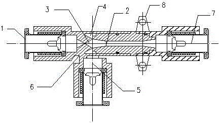
[0017] Such as figure 1 The innovation of the vacuum generator shown is that the vacuum generator includes an exhaust port 1, a Laval nozzle 2, a nozzle 3, a negative pressure chamber 4, a vacuum port 5, a housing 6 and an air inlet 7;

[0018] The exhaust port 1, the nozzle 3, the negative pressure chamber 4, the Laval nozzle 2, and the air inlet 7 are sequentially arranged in the vacuum generator housing 6, and the Laval nozzle 2 and the exhaust port 1 are connected through the nozzle 3, A vacuum port 5 is installed in the vertical direction of the nozzle 3, the negative pressure chamber 4 is located at the interface between the Laval nozzle 2 and the nozzle 3, and the air inlet 7 is connected to one end of the Laval nozzle 2;

[0019] The casing 6 has a T-shaped structu...


PUM


Abstract

The invention relates to a vacuum generator which has the innovative points that the vacuum generator comprises an exhaust port, a Laval nozzle, a nozzle, a negative pressure cavity, a vacuum port, a shell and an air inlet; the vacuum generator uses compressed air as power; according to the vacuum generator, by enabling the compressed air to enter an airflow nozzle, airflow flows out of the nozzle at a high speed, a suction effect is generated, and finally, the compressed air and the sucked air are exhausted into the atmosphere through a receiver nozzle. The vacuum generator adopting the design is simple in structure, low in manufacturing cost, small in adsorption volume, short in response time, low in surface leakage rate and low in air consumption.

Description

technical field [0001] The invention relates to a vacuum device, in particular to a vacuum generator. Background technique [0002] Vacuum generators are widely used in broadcasting, communication, television, radar, navigation, industrial automation, machinery, electronics, packaging, printing, plastics and robots. Vacuum generators need to absorb and transport various materials, especially suitable for adsorption Fragile, soft, thin non-ferrous, non-metallic materials or spherical objects, ordinary vacuum generators use vacuum pumps driven by motors, which generate high energy consumption, large volume, heavy weight and require regular maintenance. [0003] In addition, during the application process, ordinary vacuum generators have unstable pumping volume, difficult control of vacuum degree, and inaccurate intermittent time during intermittent work, resulting in inaccurate vacuum generator movements. Contents of the invention [0004] The technical problem to be solved...

Claims


Application Information

Patent Timeline
IPC IPC(8): F04F5/20F04F5/46
CPCF04F5/20F04F5/46
Inventor 周亚宏
Owner NANTONG HONGDA MECHANICAL & ELECTRONIC CO LTD
Why Eureka
Try Eureka