
High-precision flow servo control valve
A servo control, high-precision technology, applied in the direction of valve details, safety valves, balance valves, etc., can solve the problems of not meeting certain requirements, affecting the design performance of rocket engines, and low precision, so as to achieve stable work and flow regulation The effect of stable and high flow control accuracy
- Summary
- Abstract
- Description
- Claims
- Application Information
AI Technical Summary
Problems solved by technology
Method used
Image

Examples
Embodiment Construction
[0023] specific implementation plan
[0024] Below in conjunction with accompanying drawing, the patent of the present invention is described further.
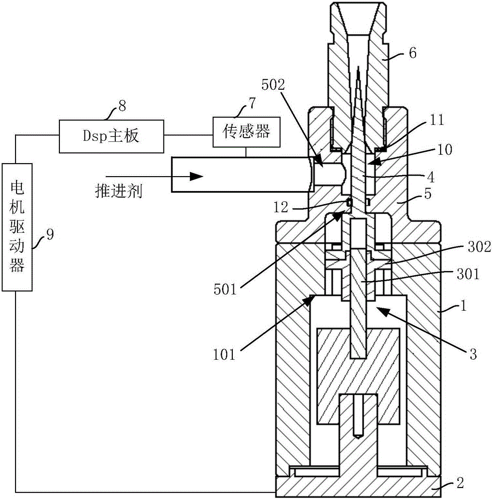
[0025] The high-precision flow servo control valve of the present invention includes a casing 1, a servo motor 2, a ball screw 3, an adjusting cone 4, a valve body 5, a venturi tube 6, a sensor 7, a Dsp main board 8 and a motor driver 9, such as figure 1 shown.
[0026] The casing 1 is a cylindrical structure made of LY12 aluminum alloy; the servo motor 2 is arranged coaxially with the casing 1 , and the front end is fixed and fixed at the end of the casing 1 so that the output shaft of the servo motor 2 is located in the casing 1 . The ball screw 3 is arranged in the housing 1 , and the screw 301 of the ball screw 3 is coaxially connected with the output shaft of the servo motor 2 through a coupling. The nut 302 of the ball screw 3 cooperates circumferentially with the inner ring side wall of the annular positioning boss A1...
PUM
 Abstract
Description
Claims
Application Information