Dangerous waste swirl-flow melting system and dangerous waste treatment and recycling method thereof

A hazardous waste and cyclone technology, applied in the combustion method, combustion type, incinerator, etc., can solve the problems of low combustion efficiency, high carbon content in ash and slag, high dioxin content, and achieve reasonable and simple layout and stable operation. Effective, easy-to-implement effects

Active Publication Date: 2016-07-13
国泥工程中心(哈尔滨)有限公司
View PDF4 Cites 1 Cited by
  • Summary
  • Abstract
  • Description
  • Claims
  • Application Information

AI Technical Summary

Problems solved by technology

In short, the problems of high dioxin content, high carbon content in ash and low combustion efficiency in the existing treatment methods have not been effectively solved

Method used


Image

  • Dangerous waste swirl-flow melting system and dangerous waste treatment and recycling method thereof
  • Dangerous waste swirl-flow melting system and dangerous waste treatment and recycling method thereof
  • Dangerous waste swirl-flow melting system and dangerous waste treatment and recycling method thereof

Examples


specific Embodiment approach 1

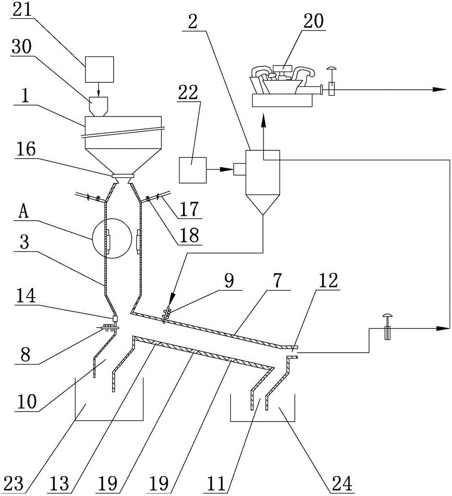
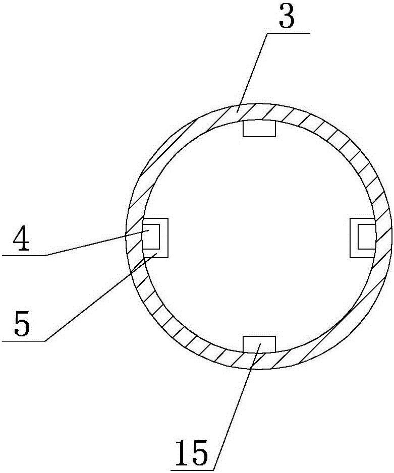
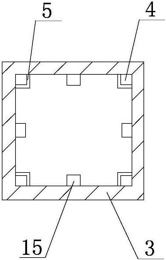
[0033] Specific implementation mode one: combine figure 1 , figure 2 , image 3 and Figure 4Describe this embodiment, this embodiment includes a vertical combustion chamber assembly, a horizontal combustion chamber assembly, a crushing device 1 and a waste liquid drying device 2, the vertical combustion chamber assembly includes a vertical combustion cylinder 3, the vertical combustion chamber The combustion tube 3 is vertically arranged, and the top of the vertical combustion tube 3 is connected with a crushing device 1, and the wall of the vertical combustion tube 3 is sequentially processed with a plurality of top burn-off air nozzles 4 and a plurality of primary air nozzles. 5 and a plurality of secondary air nozzles 6, the horizontal combustion chamber assembly includes a horizontal combustion cylinder 7, a secondary combustion burner 8, a powder burner 9, a first discharge pipe 10 and a second discharge pipe 11, the The horizontal combustion cylinder 7 is located be...

specific Embodiment approach 2

[0064] Specific implementation mode two: combination figure 2 and image 3 To describe this embodiment, in this embodiment, a plurality of split burn-off air nozzles 15 are also processed on the cylinder wall of the vertical combustion cylinder 3 . This setting cooperates with multiple top burn-off air nozzles 4, multiple primary air nozzles 5 and multiple secondary air nozzles 6 to ensure that the four corners are tangentially circled and generate strong swirling flow, so that the vertical combustion tube 3 can fully burn High melting point characteristics.

[0065] It is feasible for the present invention to reach the temperature condition for melting hazardous wastes without adding auxiliary fuel, but some auxiliary means are needed. The calculation results show that the effect of increasing the furnace temperature by controlling the lower air excess coefficient is very limited. And increasing the air distribution ratio of primary air and secondary air can effectively i...

specific Embodiment approach 3

[0067] Specific implementation mode three: combination figure 1 To illustrate this embodiment, the vertical combustion chamber assembly in this embodiment further includes a sealing sleeve 16 , and a sealing sleeve 16 is provided between the crushing device 1 and the vertical combustion cylinder 3 . In this embodiment, the setting of the sealing sleeve 16 is to ensure the tightness of the crushing device 1 and the vertical combustion cylinder 3, so as to prevent the combustion efficiency of hazardous wastes from being affected by air leakage and ensure efficient combustion in the vertical combustion cylinder 3. Other unmentioned structures and connection methods are the same as those in the second embodiment.


PUM


Abstract

The invention provides a dangerous waste swirl-flow melting system and a dangerous waste treatment and recycling method thereof, and relates to a dangerous waste melting system and a treatment and recycling method thereof. Effective melting and toxin-free discharging effects of existing solid-state or liquid-state dangerous wastes cannot be easily realized in a treatment process, the ignition stability is not high and the heat energy utilization rate is poor. The top of a vertical type combustion barrel is communicated with a crushing device; a horizontal type combustion barrel is located under the vertical type combustion barrel and one end of the horizontal type combustion barrel is communicated with the vertical type combustion barrel; a primary air inlet is formed in the part, close to a barrel wall at one end of the vertical type combustion barrel, of the horizontal type combustion barrel; a secondary combustion-supporting combustor is located on the barrel wall of the horizontal type combustion barrel and is arranged nearby the primary air inlet; and a waste liquid drying device is located above the horizontal type combustion barrel and is communicated with the horizontal type combustion barrel through a powder combustor. The dangerous waste treatment and recycling method comprises the following steps: step 1: carrying out primary treatment; step 2: carrying out primary melting; step 3: drying waste liquid; step 4: carrying out secondary melting; and step 5, recycling residual heat. The dangerous waste swirl-flow melting system and the dangerous waste treatment and recycling method are used for treating dangerous wastes.

Description

technical field [0001] The invention specifically relates to a hazardous waste cyclone melting system and a method for treating and recycling hazardous waste. Background technique [0002] In recent years, both the public health impact and the transboundary movement of hazardous waste have continued to be hot topics around the world. As one of the developing countries with the fastest GDP growth rate, our country is also facing the problem of hazardous waste. Environmental accidents and hazards caused by hazardous waste often last for a long time, are highly concealed, and have serious consequences; once a pollution accident occurs, environmental pollution control will cost a huge amount of money, and ecological restoration will take longer, and sometimes it is even difficult to restore. Therefore, it is a key issue to strengthen the management of hazardous waste and realize the harmless treatment of hazardous waste. [0003] Hazardous waste mainly involves three areas: in...

Claims


Application Information

Patent Timeline
Patent Type & Authority Applications(China)
IPC IPC(8): F23G7/00F23G7/04
CPCF23G7/00F23G7/008F23G7/04F23G2201/10F23G2201/80F23G2202/102F23G2202/103F23G2203/30F23G2206/00F23G2209/10F23G2900/50001
Inventor 郭馨赵广播高建民杜谦
Owner 国泥工程中心(哈尔滨)有限公司
Why Eureka
Try Eureka