Tail heat utilized hot-air type penetration countercurrent fluidized drying machine

A technology of fluidized drying and tail heat, which is applied in the direction of dryers, drying solid materials, drying gas arrangement, etc., can solve problems such as difficulty in disassembly, and achieve the effects of eliminating fatigue fracture, reliable use, and saving materials

Active Publication Date: 2016-07-13
安徽上元家居材料股份有限公司
View PDF6 Cites 3 Cited by
  • Summary
  • Abstract
  • Description
  • Claims
  • Application Information

AI Technical Summary

Problems solved by technology

In the actual assembly of shafts and holes with transmission threads, in order to achieve large load-bearing functions, the size of the threaded shafts and matching nut-like components are relatively large, and it is often easy and convenient to screw in during assembly, and It can realize the automatic and continuous locking of the bearing capacity during use, so it is very reliable, but when it is disassembled, the assembly is often very tight, and disassembly is very difficult. It is particularly important to realize simple and easy disassembly under this condition

Method used


Image

  • Tail heat utilized hot-air type penetration countercurrent fluidized drying machine
  • Tail heat utilized hot-air type penetration countercurrent fluidized drying machine
  • Tail heat utilized hot-air type penetration countercurrent fluidized drying machine

Examples


Embodiment Construction

[0035] Now in conjunction with accompanying drawing, the present invention is described in further detail.

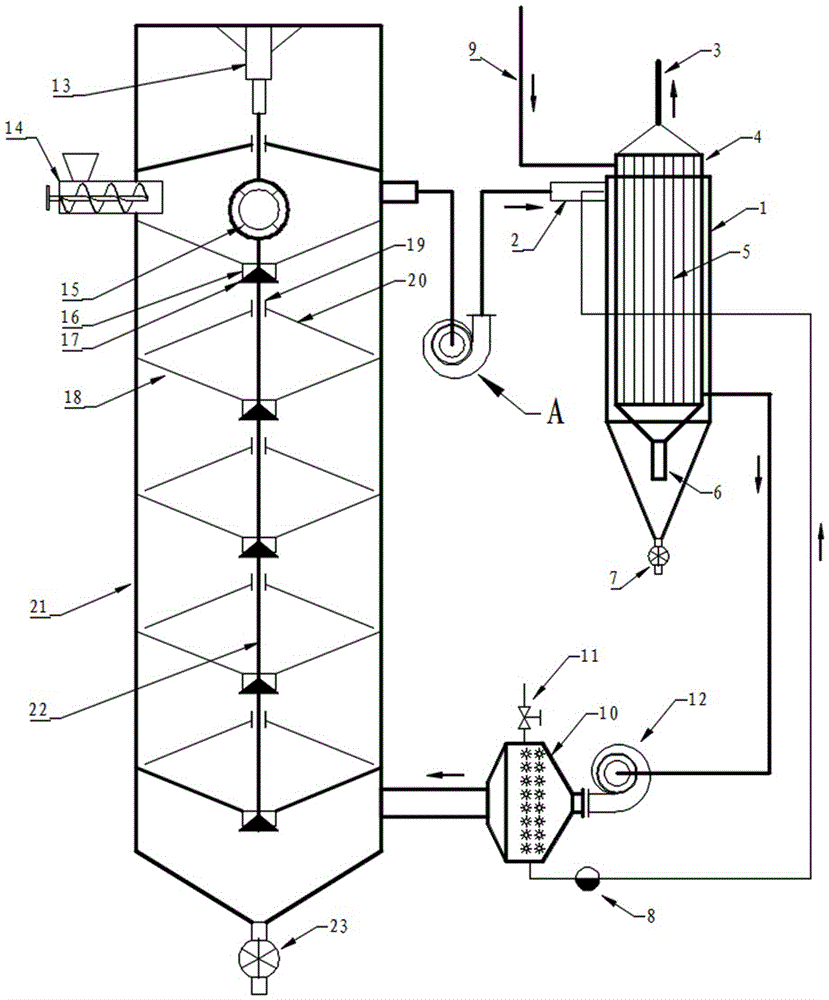
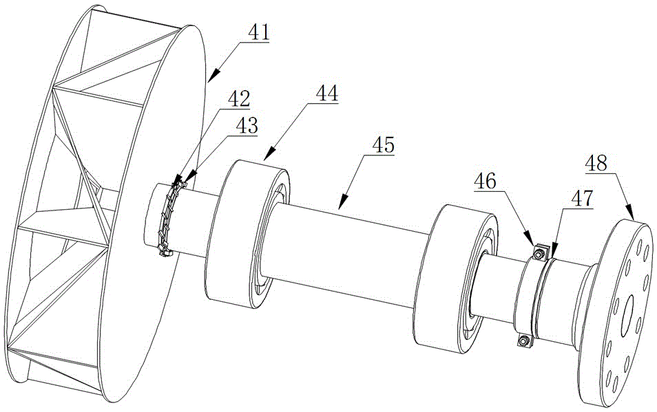
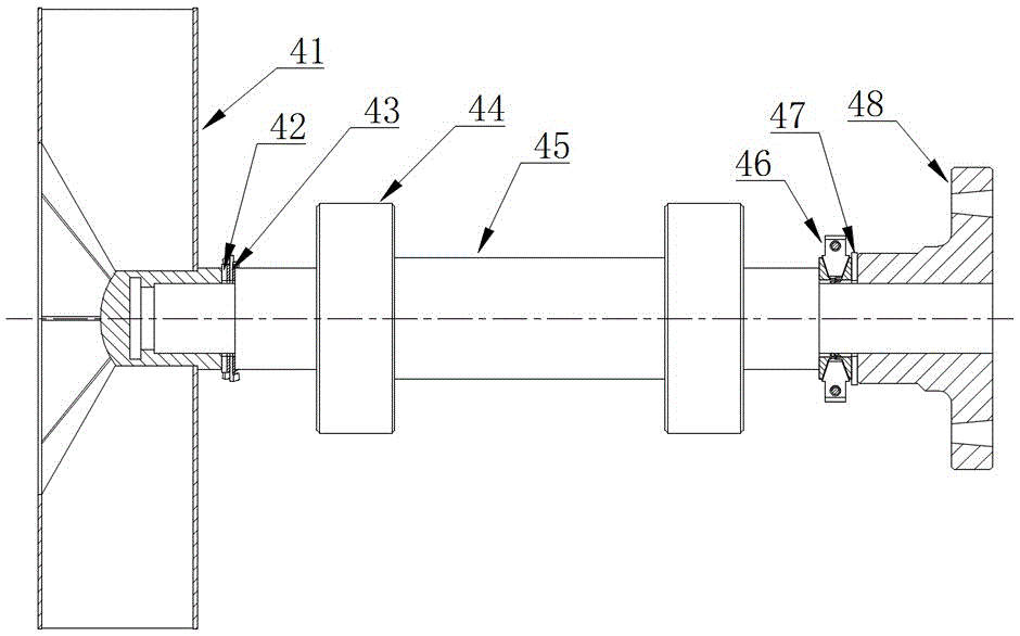
[0036] like figure 1 , figure 2 , image 3 , Figure 4 , Figure 5 , Image 6 , Figure 7 , Figure 8 and Figure 9 The shown tail heat utilization hot air penetrating countercurrent fluidization dryer includes a drying tower 21 and an induced draft fan A. The upper part of the drying tower A is provided with a material-sealed screw feeder 14, and the bottom is provided with an air lock discharger 23; The upper part is connected to the induced draft fan A, and the induced draft fan A is tangentially connected to the high-efficiency recovery device for the tail heat of the cyclone dust collector formed by the superposition of the tube-and-tube heat exchanger 4 and the cyclone dust collector 1, and then emptied; The gas end is connected to the atmosphere, and the gas outlet is connected to the lower part of the drying tower 21 through the blower 12 and the steam ...


PUM


Abstract

The invention discloses a tail heat utilized hot-air type penetration countercurrent fluidized drying machine. A draught fan is connected to the upper part of a drying tower; the draught fan is tangentially connected with a cyclone dust removal tail heat efficient recoverer which is formed by a tube type heat exchanger and a cyclone dust collector which are overlapped, and is evacuated; the shell pass air inlet end of the tube type heat exchanger is communicated with the atmosphere; the air outlet of the tube type heat exchanger is connected to the lower part of the drying tower through an air blower and a steam fin heater; blades of the draught fan impeller are arranged in a radiation manner that impeller shafts are in radial and central symmetry; dust can be collected by virtue of centrifugal force in time, and thus security accidents can be avoided. By adopting the tail heat utilized hot-air type penetration countercurrent fluidized drying machine, the drying efficiency is improved, the purposes of energy conservation and emission reduction are achieved, more importantly, the assembling and disassembling technique of the draught fan is greatly improved, pressure caused by components such as a screw nut to the shoulder end surface of a screw shaft can be easily eliminated when the draught fan is assembled and disassembled, the problem that the draught fan is continuously automatically locked and is not easy to disassemble under the action of load in threaded assembling can be effectively solved, and the tail heat utilized hot-air type penetration countercurrent fluidized drying machine is particularly applicable to convenient and rapid disassembling after a large-size draught fan is in threaded locking and is particularly remarkable in effect.

Description

technical field [0001] The invention relates to a drying machine, which specifically refers to a hot-air penetrating countercurrent fluidization drying machine which uses tail heat without dust accumulation in the fan and is easy to disassemble and repair. Background technique [0002] Due to its mature technology, strong adaptability, low operating cost and strong reliability, the hot air dryer is still one of the main preferred equipment for drying materials. , and the effective recovery of tail heat is of special significance for improving drying efficiency and realizing energy saving and emission reduction. [0003] The induced draft fan is the key equipment of the hot air dryer. The induced draft fan is generally a centrifugal fan. The continuous, stable and reliable operation of the induced draft fan is very important for the dryer. Since most of the occasions where the dryer is used contain a certain amount of dust, the induced draft fan When working, when the airflo...

Claims


Application Information

Patent Timeline
IPC IPC(8): F26B17/12F26B25/04F26B21/00F26B25/00
CPCF26B17/1458F26B21/002F26B25/00F26B25/04Y02P70/10
Inventor 张旭银永忠张思言
Owner 安徽上元家居材料股份有限公司
Why Eureka
Try Eureka