Heat pump type tail heat recycling inertial dust collection penetrating countercurrent fluidization drying machine

A tail heat recovery and fluidized drying technology, applied in the field of dryers, can solve problems such as difficulty in disassembly, and achieve the effects of preventing fatigue fracture, reliable use, and enhancing bearing capacity

Inactive Publication Date: 2016-06-22
山东启邦博冠科技发展有限公司
View PDF6 Cites 2 Cited by
  • Summary
  • Abstract
  • Description
  • Claims
  • Application Information

AI Technical Summary

Problems solved by technology

In the actual assembly of shafts and holes with transmission threads, in order to achieve large load-bearing functions, the size of the threaded shafts and matching nut-like components are relatively large, and it is often easy and convenient to screw in during assembly, and It can realize the automatic and continuous locking of the bearing capacity during use, so it is very reliable, but when it is disassembled, the assembly is often very tight, and disassembly is very difficult. It is particularly important to realize simple and easy disassembly under this condition

Method used


Image

  • Heat pump type tail heat recycling inertial dust collection penetrating countercurrent fluidization drying machine
  • Heat pump type tail heat recycling inertial dust collection penetrating countercurrent fluidization drying machine
  • Heat pump type tail heat recycling inertial dust collection penetrating countercurrent fluidization drying machine

Examples


Embodiment Construction

[0034] Now in conjunction with accompanying drawing, the present invention is described in further detail.

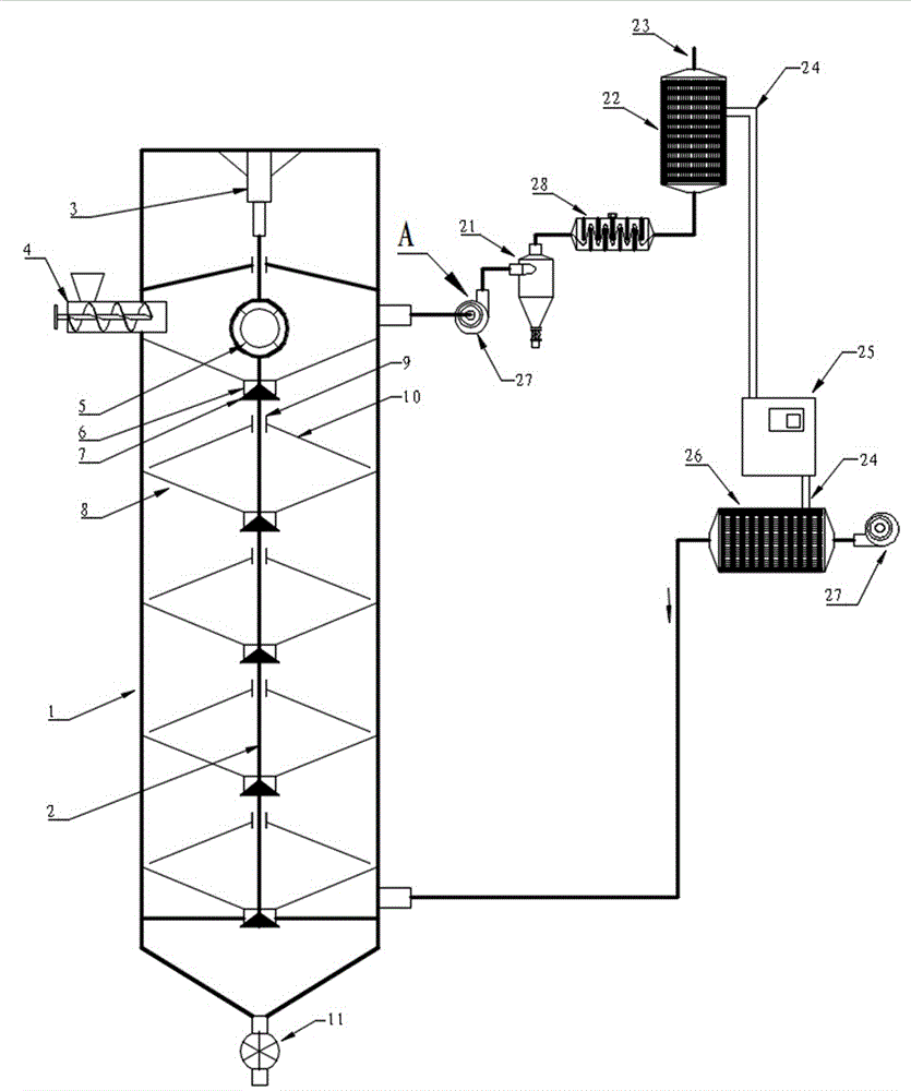
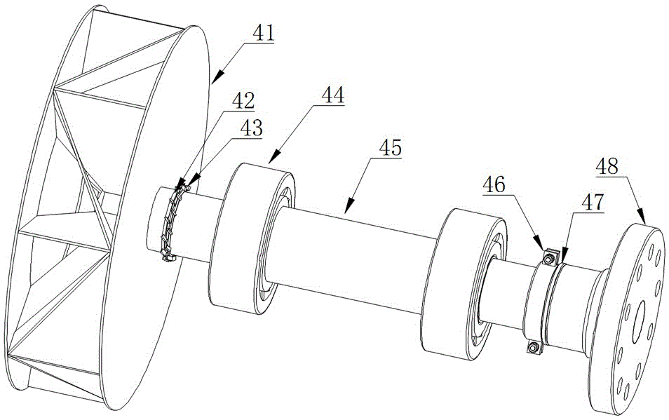
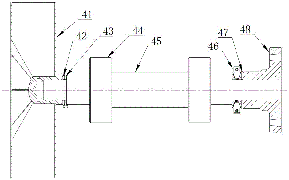
[0035] Such as figure 1 , figure 2 , image 3 , Figure 4 , Figure 5 , Image 6 , Figure 7 , Figure 8 with Figure 9 The shown heat pump tail heat recovery inertial dust removal penetrating countercurrent fluidized dryer includes a drying tower 1 and an induced draft fan A. The upper part of the drying tower is provided with a material-sealed screw feeder 4, and the bottom is provided with an air lock discharger 11; The upper part of the tower is connected to the induced draft fan A, and the induced draft fan A is connected to the evaporator 22 of the heat pump system through the cyclone dust collector 21 and the repeatedly turning baffle type inertial dust collector 28; The main engine 25 is connected to the condenser 26 through the refrigerant pipe 24; the air outlet end of the blower 27 is connected to the lower part of the drying tower through the conden...


PUM


Abstract

The invention discloses a heat pump type tail heat recycling inertial dust collection penetrating countercurrent fluidization drying machine. A material seal spiral feeder is arranged on the upper portion of a drying tower, and a closed-air aspirator discharging machine is arranged at the bottom of the drying tower; an induced draft fan is connected to the upper portion of the drying tower, and is connected with an evaporator of a heat pump system through a cyclone dust collector and a repeated reciprocating type inertial dust collector and then is subject to venting; the air outlet end of an air blower is connected with the lower portion of the drying tower through a condenser; blades of an induced draft fan impeller are arranged to be in a radiation shape in impeller shaft radial and central symmetry, centrifugal force can be used for cleaning up dust in time, and safety accidents are avoided; and according to the drying machine, the drying efficiency is improved, energy saving and emission reduction are achieved, more importantly, the dismounting and mounting technology of the induced draft fan is greatly changed, and therefore during dismounting, the pressure of similar nut components on the end face of a screw shaft shoulder can be simply eliminated; and the problem that according to the induced draft fan thread assembly, automatic locking is continuously carried out under the load effect, and dismounting is not likely to be achieved is effectively solved, and the drying machine is particularly suitable for portable dismounting of a large-scale fan obtained after thread locking, and the effect is particularly obvious.

Description

technical field [0001] The invention relates to a dryer, in particular to a heat pump tail heat recovery inertial dust removal penetrating countercurrent fluidization dryer which does not accumulate dust in a fan and is easy to disassemble and repair. Background technique [0002] People generally refer to drying with a drying temperature below 60 degrees Celsius as low-temperature drying. Low-temperature drying is widely used in the drying of heat-sensitive materials such as crop seeds, Chinese medicinal materials, and biological products. Due to its mature technology, strong adaptability, low operating cost and high reliability, hot air dryer is still one of the first choice equipment for low temperature drying. Low-temperature drying is less easy to recover tail heat due to the lower exhaust temperature. If the penetrating countercurrent fluidized drying of materials can be realized in the hot-air low-temperature drying process, and the tail heat can be effectively recov...

Claims


Application Information

Patent Timeline
IPC IPC(8): F26B17/14F26B21/00F26B25/04F26B25/00F25B30/06F26B3/092
CPCF25B30/06F26B3/0923F26B17/1475F26B21/002F26B25/007F26B25/04
Inventor 张旭银永忠张思言
Owner 山东启邦博冠科技发展有限公司
Why Eureka
Try Eureka