Pipe connection instant heating type heat exchanger with part of shell tubes storing water

A heat exchanger and connecting pipe technology, applied in the field of HVAC, can solve the problems of paying more water bills, increasing costs, and increasing product volume.

Active Publication Date: 2016-07-13
山东利能换热器有限公司
View PDF8 Cites 2 Cited by
  • Summary
  • Abstract
  • Description
  • Claims
  • Application Information

AI Technical Summary

Problems solved by technology

[0003] During the use of the above-mentioned prior art water storage heat exchangers, it was found that the cold source hot water stored in the tube lumen is generally used for one round of heating and then used for another round, and there are intermittent hot and cold water, and hot water cannot flow out continuously. Technical problems or defects in the bath
There is also the fact that the expansion pressure of cold water is greater than the water supply pressure of the tap water pipe network, causing the water meter to run backward or forward, distorting the reading of the water meter, and some users find that the actual water consumption is different from the reading of the water meter, which is different from the actual water consumption of normal households and pays more Defects in water bills
However, the thermal efficiency of heat exchangers in the prior art is not up to expectations. The cold fluid flow channel of the heat exchanger is generally short, the flow rate of the cold fluid flowing into the heat exchanger is faster than that of the hot fluid, and the outlet temperature of the heat source is higher than the outlet temperature of the cold source. The point is that the heat exchange is not complete, so the outlet temperature of the heat source is higher than the outlet temperature of the cold source
After comparative tests, the water storage heat exchanger relies on the stored hot water to prolong the exchange time, and the heat exchange effect is not ideal. The hot water stored in the heat exchanger is quickly used up when taking a bath, and the subsequent heating cannot keep up. The temperature, flow rate or The flow rate and the flow rate of the cold source or the flow rate and the return trip are short and the exchange time is short and insufficient. The heat absorbed by the new cold water flowing into the heat exchanger is not proportional to the heat taken away by the user's nozzle, resulting in the exchange temperature not being connected and interrupted. Complete Defects or phenomena that need to wait for heating before taking a bath
Water storage heat exchangers must increase the volume of the product to solve the problem of being able to bathe, that is to say, increasing the number of columns or increasing the pipe diameter increases the amount of water stored to meet the requirements, which will inevitably lead to increased costs, increased steel consumption and waste of resources
At present, the temperature of the heating heat source is relatively low and the logarithmic temperature difference is relatively small. The existing technology structure is no longer applicable, resulting in the outlet temperature of the cold source of the heat exchanger fluctuating hot and cold, high and low, hot water cannot flow out continuously, and the effect is poor, so it is eliminated.

Method used


Image

  • Pipe connection instant heating type heat exchanger with part of shell tubes storing water
  • Pipe connection instant heating type heat exchanger with part of shell tubes storing water
  • Pipe connection instant heating type heat exchanger with part of shell tubes storing water

Examples


Embodiment Construction

[0033]The present invention will be further described below in conjunction with the accompanying drawings and specific embodiments.

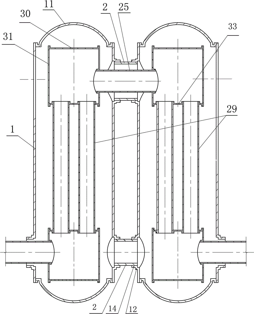
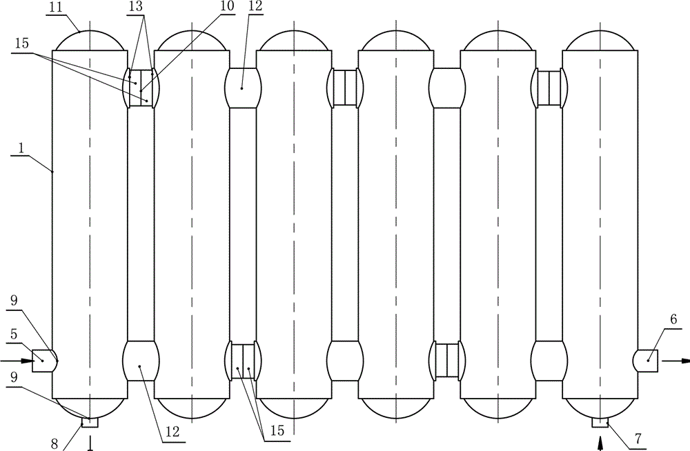
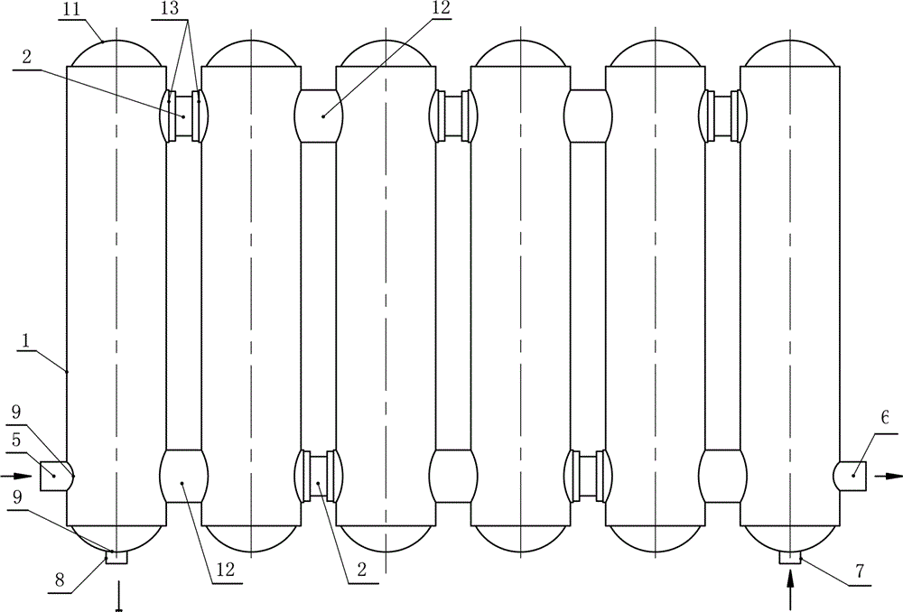
[0034] 1. The pipe of the present invention connects part of the shell-and-tube water storage heat exchanger, such as Figure 1 to Figure 25 As shown, it includes: shell tube 1, head blocking plate 11, cold water heat-absorbing pipe 3, heating pipe 24, heating connecting pipe 25, pipe connecting partition 26, pipe joints and other components assembled and welded to form a radiator-shaped heat exchanger; Ports of multiple shell tubes 1 are locally positioned and have shell tube Unicom welding holes 10 or notches 21 at the mouth of the tubes. The holes or slots on the shell tubes 1 are connected to the adjacent tubes by airtight welding. The cavity is connected to form a fluid heat conduction circulation channel; the port of the shell tube 1 is not perforated, and the wall of the tube is provided with a support 12 to support and fix the adjacent t...


PUM


Abstract

The invention discloses a pipe connection instant heating type heat exchanger with part of shell tubes storing water.A pipe connection partition board is arranged at the position of a shell tube connection welding hole, and a partition board connection pipe welding hole and a partition board cold water pipe welding pipe are formed in the pipe connection partition board so as to facilitate welding connection; at least one cold water heat absorption pipe is arranged in cavities of part of shell tubes, and heating pipes are arranged in cavities of part of shell tubes; the port, welded and communicated with the heating pipes, of a central heating connection pipe is inserted into a pipe connection partition board hole and communicated with the inner cavity of the adjacent shell tube, so that the fluid channel, pipe diameter and circulating heat transmission flow path are changed; an orifice of each cold water heat absorption pipe is inserted into the pipe connection partition board hole to be communicated with the inner cavity of the adjacent shell tube, so that the fluid channel, pipe diameter and circulating heat absorption flow path are changed.The circulating path of heat storage water in the cavities of part of shell tubes changes to increase return heating of built-in cold water thin pipes, flow and flow rate are reduced, exchange route is lengthened, sufficient exchange space is gained, heat exchange rate is increased fast, and the expectation of maximizing heat exchange effect is realized.

Description

technical field [0001] The invention relates to the field of heating and ventilation technology, and uses heating as a heat source to exchange hot water for office and household heating heat exchangers, in particular to a heat exchanger made of stainless steel or copper pipes connected with a part of the shell tube for water storage. Background technique [0002] The applicant applied for it on September 8, 2013. The name of the invention is "a shell water storage heating pipe diversion heat conduction heat exchanger and its manufacturing process", the authorized announcement number: CN103438737B, and the authorized announcement date: April 8, 2015 Japan, patent number: 2013104028088. It was applied again on February 23, 2014, and the title of the invention is "Unicom tube pressure-bearing multi-tube heating water storage heat exchanger and its manufacturing process", authorized announcement number: CN103791738B, authorized announcement date: October 21, 2015 , Patent No.: ...

Claims


Application Information

Patent Timeline
Patent Type & Authority Applications(China)
IPC IPC(8): F28D7/10F28F9/26F28F1/04
CPCF28D7/10F28F1/04F28F9/262
Inventor 张伟张冲
Owner 山东利能换热器有限公司
Why Eureka
Try Eureka