Geotechnical centrifuge driven by synchronous belt transmission device

A technology of synchronous belt drive and geotechnical centrifuge, which is applied in the direction of soil material testing and material inspection, and can solve the problems of motor size increase, reducer structural design restrictions, and endangering motor operation safety, so as to achieve reliable operation and convenient maintenance And replacement, the effect that the structure is simple

Active Publication Date: 2016-07-13
GENERAL ENG RES INST CHINA ACAD OF ENG PHYSICS
View PDF8 Cites 2 Cited by
  • Summary
  • Abstract
  • Description
  • Claims
  • Application Information

AI Technical Summary

Problems solved by technology

[0007] 1) When the motor is used to drive, the motor is directly connected to the main shaft of the centrifuge. When the centrifuge is running, the impact force caused by the unbalanced arm will directly act on the motor through the main shaft, which will endanger the operation safety of the motor, especially for centrifuges. In earthquake simulation, this hazard is even greater; in addition, when the size of the main shaft of the centrifuge is large, the size of the motor will increase accordingly, increasing the construction cost of the centrifuge
[0008] 2) When driven by a motor and a reducer, the reducer acts as a transition link between the motor and the centrifuge spindle, which can alleviate the impact of the additional force generated during the operation of the centrifuge on the motor, but this additional force is transmitted by the reducer Bearing, and directly transmitted to the building foundation where the reducer is installed; In addition, due to the influence of the size of the main shaft of the centrifuge and the transmission ratio of the reducer, the structural design of the reducer is subject to certain restrictions

Method used


Image

  • Geotechnical centrifuge driven by synchronous belt transmission device
  • Geotechnical centrifuge driven by synchronous belt transmission device
  • Geotechnical centrifuge driven by synchronous belt transmission device

Examples


Embodiment Construction

[0028] The present invention will be further described below in conjunction with accompanying drawing:

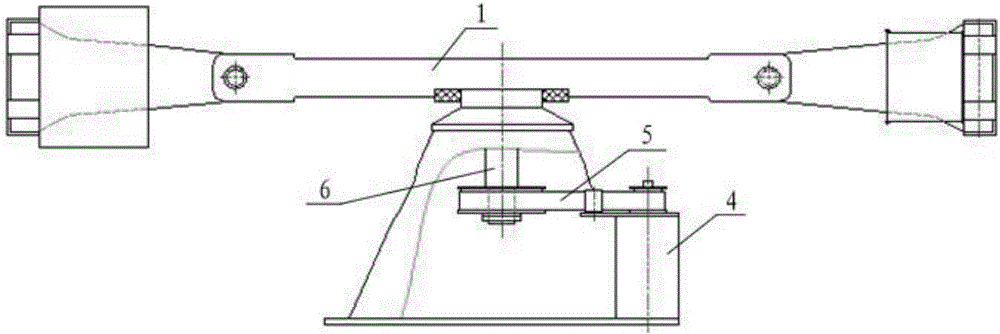
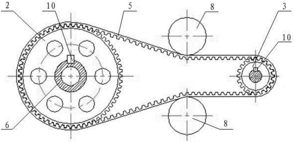
[0029] Such as figure 1 , figure 2 , image 3 and Figure 4 As shown, the present invention comprises a vertically installed main shaft 6 and a motor 4, the upper end of the main shaft 6 is horizontally provided with a rotating arm 1, the lower end of the main shaft 6 is provided with a large pulley 2, and the rotating shaft of the motor 4 is provided with a small pulley 3, and the small The belt pulley 3 and the large pulley 2 are connected through a synchronous belt 5, and two tension pulleys 8 are arranged on the outside of the synchronous belt 5.

[0030] The synchronous belt 5 is used to connect the small pulley 3 and the large pulley 2 to realize the transmission of the fixed transmission ratio from the small pulley 3 to the large pulley 2 . Tension pulley 8 is used to adjust the meshing position of synchronous belt 5 and large pulley 2, synchronous belt 5 and sm...


PUM


Abstract

The invention discloses a geotechnical centrifuge driven by a synchronous belt transmission device. The geotechnical centrifuge driven by the synchronous belt transmission device comprises a main shaft and a motor which are mounted vertically; a rotating arm is horizontally arranged at the upper end of the main shaft; a large belt wheel is arranged at the lower end of the main shaft; a rotating shaft of the motor is provided with a small belt wheel; the small belt wheel is in transmission connection with the large belt wheel through a synchronous belt; two tensioning wheels are arranged on the outer side of the synchronous wheel. According to the geotechnical centrifuge driven by the synchronous belt transmission device, a layered construction structure which is driven by adopting the motor or driven by the motor and a speed reducer in the prior art is changed, and the construction cost is lowered; the requirement on continuously supplying a large amount of water, oil and gas to the rotating arm through an inner hole of the main shaft when the centrifuge operates can be met; the synchronous belt has certain effects on vibration damping and noise reducing; an additional acting force generated by imbalance of the rotating arm or vibration of a vibrating table can be absorbed to a certain degree, and the impact on a construction foundation caused by the additional acting force is reduced; the synchronous belt is reliable in work, simple in structure, and convenient to maintain and replace.

Description

technical field [0001] The invention relates to a geotechnical centrifuge, in particular to a geotechnical centrifuge driven by a synchronous belt transmission device. Background technique [0002] The geotechnical centrifuge uses the high-speed rotating arm to generate a supergravity field environment. By installing related test devices (such as: manipulator device, earthquake simulation device, wind device and deep sea environment simulation device, etc.) The simulation of load conditions (such as: opening, digging, earthquake process, ocean storm process and deep sea operation process, etc.) provides a basic test platform for excavation of geotechnical structure foundation pit, earthquake damage mechanism research and marine resource development. [0003] In order to ensure the accuracy and reliability of the simulation test in the supergravity field, it is necessary to ensure that the supergravity field environment provided by the high-speed rotation of the centrifuge ar...

Claims


Application Information

Patent Timeline
Patent Type & Authority Applications(China)
IPC IPC(8): G01N33/24
CPCG01N33/24
Inventor 李心耀洪建忠黎启胜李明海赵宝忠
Owner GENERAL ENG RES INST CHINA ACAD OF ENG PHYSICS
Why Eureka
Try Eureka