Supercharge Your Innovation With Domain-Expert AI Agents!

Splitter, multimode laser test assembly and optical module test system

A technology for testing components and lasers, which is applied in the field of optical communications, can solve the problems of connection loss increasing noise signals, restricting the specification and unification of multi-mode optical transceiver modules, and distorting test results, achieving low cost, accurate testing, convenience and feasibility, The effect of guaranteeing authenticity

Active Publication Date: 2016-07-13
WUHAN TELECOMM DEVICES
View PDF5 Cites 0 Cited by
  • Summary
  • Abstract
  • Description
  • Claims
  • Application Information

AI Technical Summary

Problems solved by technology

The splitters and attenuators used in conventional testing of optical modules not only change the amplitude of the optical signal, but also change its phase, resulting in distortion of the test results
On the other hand, more mode injection, especially the injection of a large number of high-order modes, will not only increase the mode dispersion, but also increase the injection connection loss and generate noise signals caused by bending distortion, which seriously affects normal use.
Therefore, the testing of multimode fiber laser components and optical modules has attracted more and more attention from the industry. The Encircledflux testing equipment developed by the British arden company and the American pk company can better test the light source injection mode, but its high cost and cumbersome The operation is not conducive to the popularization of mass production, which in turn limits the standardization and unification of multi-mode optical transceiver modules

Method used


Image

  • Splitter, multimode laser test assembly and optical module test system
  • Splitter, multimode laser test assembly and optical module test system
  • Splitter, multimode laser test assembly and optical module test system

Examples


Embodiment 1

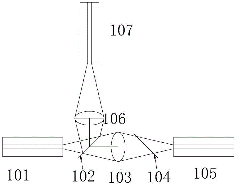
[0046] Such as figure 1 As shown, it is a schematic structural diagram of an optical splitter provided by Embodiment 1 of the present invention. An embodiment of the present invention aims at the problem that it is difficult for the optical splitter in the prior art to realize that the phase distribution of the light source signal does not change, and provides an optical splitter, the optical splitter at least includes:

[0047]One light input port, two light output ports, a first lens and a second lens of the same specification placed between the input port and the output port, and a beam splitter and a glass slide of equal thickness; wherein, the input port is placed At twice the focal length of the first lens; the beam splitter is placed between the first lens and the input port; the first output port is placed on the other side of the first lens opposite to the input port at twice the focal length on one side; the glass slide is placed between the first lens and the first...

Embodiment 2

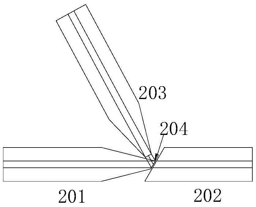
[0050] Such as figure 2 As shown, it is a schematic structural diagram of another optical splitter provided by Embodiment 2 of the present invention. The optical splitter at least includes: one optical input port and two optical output ports; wherein, the end face of the optical fiber access end at the input port and the end face of the optical fiber access end at the first output port are ground to a preset value The inclination angle, and the optical fiber access end at the input port is coated with a spectroscopic film to ensure seamless connection between the optical fiber at the input port and the optical fiber at the first output port.

[0051] Preferably, by grinding the input optical fiber 401 of the optical input port into a slope of a preset numerical angle, for example, the preset value is 30°, and coating a 3dB light-splitting film; simultaneously grinding the output optical fiber 402 at the first output port into a The slope at the same angle ensures that the in...

Embodiment 3

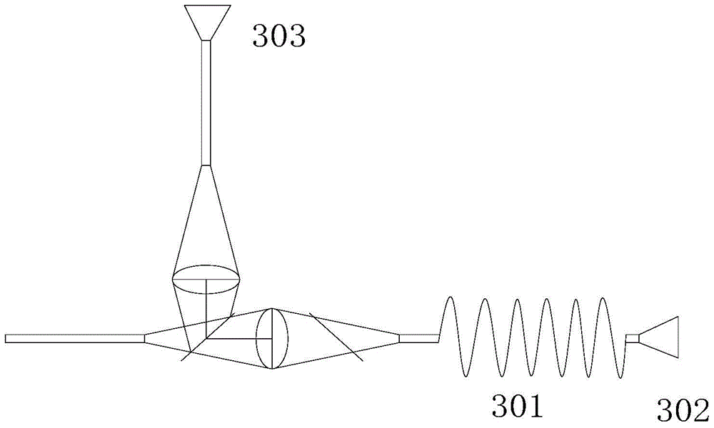
[0053] Such as image 3 As shown, it is a schematic structural diagram of a multimode laser test assembly provided by Embodiment 3 of the present invention. The multimode laser test assembly at least includes: an optical splitter, a mode winder, and a detector as in the first embodiment above; wherein, the mode winder is placed at the first output port or the second output port port; the first output port and the second output port are respectively equipped with a first detector and a second detector, by comparing the difference in optical power received by the first detector and the second detector Screen the mode distribution of the light source injected into the fiber of the multimode optical module.

[0054] Preferably, the multimode laser test component utilizes the optical splitter described in Embodiment 1, and adds a fixed-diameter, number-of-turn mode-winder 201 on one of the output branches of the above-mentioned optical splitter, and connects the output port The o...


PUM


Abstract

The invention provides an optical splitter, which at least comprises an optical input port, two optical output ports, a first lens and a second lens arranged between the input port and the output ports, and a light splitter and a glass slide, wherein the input port is arranged at a twofold focal length of the first lens; the light splitter is arranged between the first lens and the input port; the first output port is arranged at a twofold focal length of the other side, deviating from the input port, of the first lens; the glass slide is arranged between the first lens and the first output port; the second output port is arranged at a twofold focal length of the second lens; and the optical path of the first output port and the optical path of the second output port are completely symmetrical with the optical path of the input port respectively. The splitter, the multimode laser test assembly and the optical module test system provided by the invention have the advantages of low cost, accurate test, convenience and feasibility, and test requirements by products of the kind can be met.

Description

technical field [0001] The invention relates to the technical field of optical communication, in particular to a splitter, a multimode laser test assembly and an optical transceiver module test system. Background technique [0002] With the rapid development of communications and the Internet, video services and search services with large data volumes have grown rapidly, which has greatly driven the data center market based on supercomputers and storage. In short-distance interconnection applications, VCSEL (Vertical Cavity Surface Emitting Laser, Vertical Cavity Surface Emitting Laser) chips have been widely used and popularized due to their advantages of high speed, high parallel density, and low power consumption. [0003] The transmission module based on the VCSEL chip uses multimode optical fiber to build the transmission system, which makes the optical device coupling and assembly process simple and the coupling efficiency is improved. But it is obvious that the large...

Claims


Application Information

Patent Timeline
Patent Type & Authority Applications(China)
IPC IPC(8): G02B27/10H04B10/07
CPCG02B27/106H04B10/07H04B10/0795
Inventor 王雨飞曹芳秦艳杨昌霖
Owner WUHAN TELECOMM DEVICES
Features
  • R&D
  • Intellectual Property
  • Life Sciences
  • Materials
  • Tech Scout
  • Unparalleled Data Quality
  • Higher Quality Content
  • 60% Fewer Hallucinations
Learn More