Thin film inductor and power switching circuit

A technology of thin film and inductance, which is applied in the direction of circuits, inductors, printed inductors, etc., can solve the problem of easy saturation of the magnetic core of magnetic thin film materials

Active Publication Date: 2016-07-13
HUAWEI TECH CO LTD
View PDF4 Cites 20 Cited by
  • Summary
  • Abstract
  • Description
  • Claims
  • Application Information

AI Technical Summary

Problems solved by technology

[0005] This application proposes a thin-film inductor and power conversion circuit to solve the problem that the magnetic core of magnetic thin-film material is easily saturated

Method used


Image

  • Thin film inductor and power switching circuit
  • Thin film inductor and power switching circuit
  • Thin film inductor and power switching circuit

Examples


preparation example Construction

[0200] Figure 10 is a schematic flowchart of a method 900 for manufacturing a thin film inductor according to an embodiment of the present invention. Such as Figure 10 As shown, the preparation method 900 includes:

[0201] S910, forming more than two lower layer windings;

[0202] S920, forming a thin film magnetic core, the thin film magnetic core includes a plurality of magnetic columns, a first end and a second end opposite to the first end, the plurality of magnetic columns are isolated from each other, and the plurality of magnetic columns The magnetic columns are all rod-shaped. One end of each magnetic column in the plurality of magnetic columns is in contact with the first end, and the other end is in contact with the second end. The plurality of magnetic columns include more than two winding magnetic columns and more than one non-winding magnetic columns; the thin film magnetic core includes at least one layer of magnetic film, each layer of magnetic film is lo...


PUM

PropertyMeasurementUnit
widthaaaaaaaaaa
widthaaaaaaaaaa
widthaaaaaaaaaa

Abstract

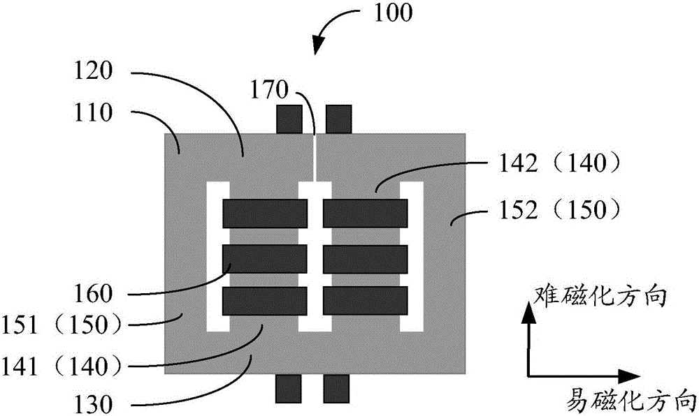
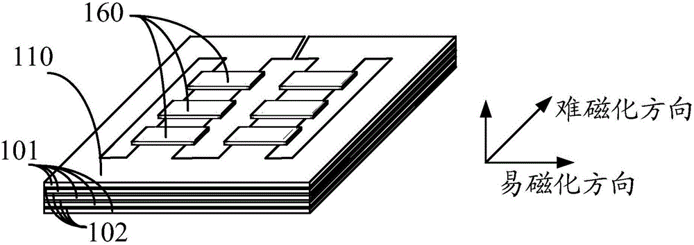
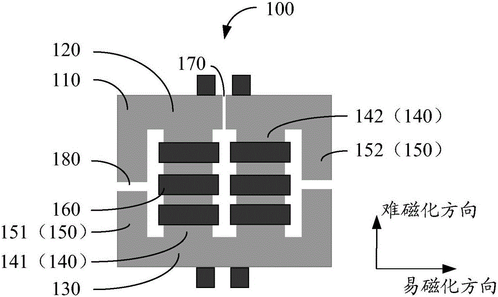
The invention discloses a thin film inductor which comprises a thin film magnetic core. The thin film magnetic core comprises multiple magnetic columns, a first end and a second end. The multiple magnetic columns are arranged at intervals and are in a rod shape. One end of each magnetic column makes contact with the first end, and the other end of each magnetic column makes contact with the second end. The multiple magnetic columns comprise two or more winding magnetic columns and one non-winding magnetic column which is located on one side of the winding magnetic columns; or the multiple magnetic columns comprise two or more winding magnetic columns and two non-winding magnetic columns, wherein the winding magnetic columns are located between the two non-winding magnetic columns. The thin film magnetic core comprises at least one layer of magnetic thin film. The area, located at the first end and the second end and located between the adjacent winding magnetic columns, in each layer of magnetic thin film is provided with at least one first gap. The length direction of each first gap is parallel to the difficult magnetization direction of the corresponding magnetic thin film. The magnetic thin films are stacked and overlaid, and the sum of the widths of all the first gaps in each layer of magnetic thin film is the same.

Description

technical field [0001] The invention relates to the field of circuits, and more particularly, to a thin film inductor and a power conversion circuit. Background technique [0002] The power conversion system of the chip power supply is developing in the direction of miniaturization, and the main device in the power conversion system, the inductance, has a large volume and is difficult to integrate into the processor. At present, there is known a high-frequency silicon-based copper-magnet-copper (CopperMagneticCopper, "CMC") magnetic film inductor, whose thin-film magnetic core is formed by stacking multiple magnetic thin films, and the shape may be a closed square. [0003] However, due to the anisotropic characteristics of the magnetic film, the magnetic properties of the magnetic film are different in different directions, and have very large differences. If the inductance is designed along the direction that is difficult for magnetic flux to flow, in the formed magnetic ...

Claims


Application Information

Patent Timeline
Patent Type & Authority Applications(China)
IPC IPC(8): H01F17/00H01F17/04H01F27/30H02M3/155
CPCH01F17/0006H01F17/045H01F27/306H02M3/155H01F2017/0066H01F3/14H01F27/245H01F27/38H01F27/25H01F27/2804H01F2027/2809H01F17/00H01F27/30H01F17/04H01F27/24H01F41/0206
Inventor 杨和钱朱勇发骆孝龙
Owner HUAWEI TECH CO LTD
Why Eureka
Try Eureka