Magnetic induction pipeline generator
A generator and magnetic induction technology, applied in the direction of engines, wind power generation, engine components, etc., can solve problems such as large resistance, hidden safety hazards, and unpopularization, and achieve the effects of large output power, reliable power supply guarantee, and improved reliability
- Summary
- Abstract
- Description
- Claims
- Application Information
AI Technical Summary
Problems solved by technology
Method used
Image

Examples
Embodiment 1
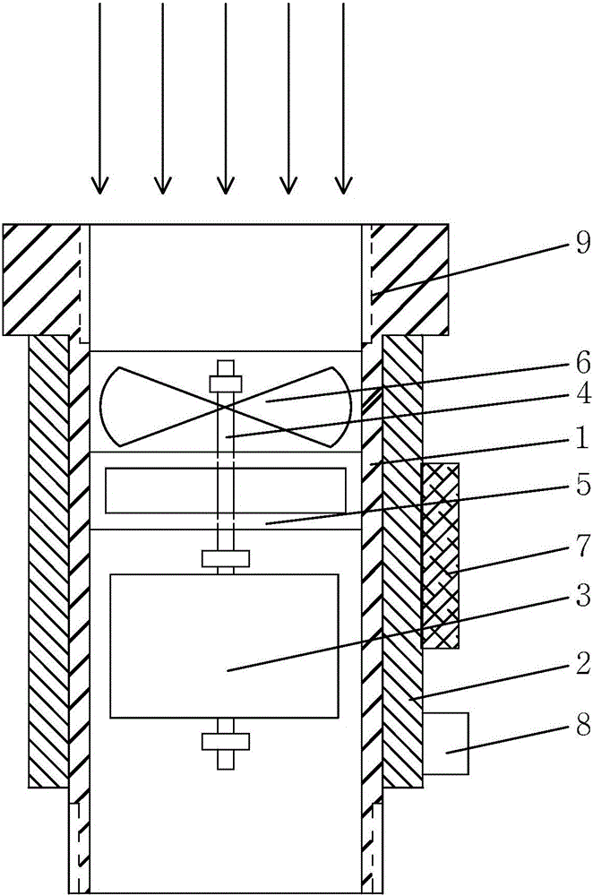
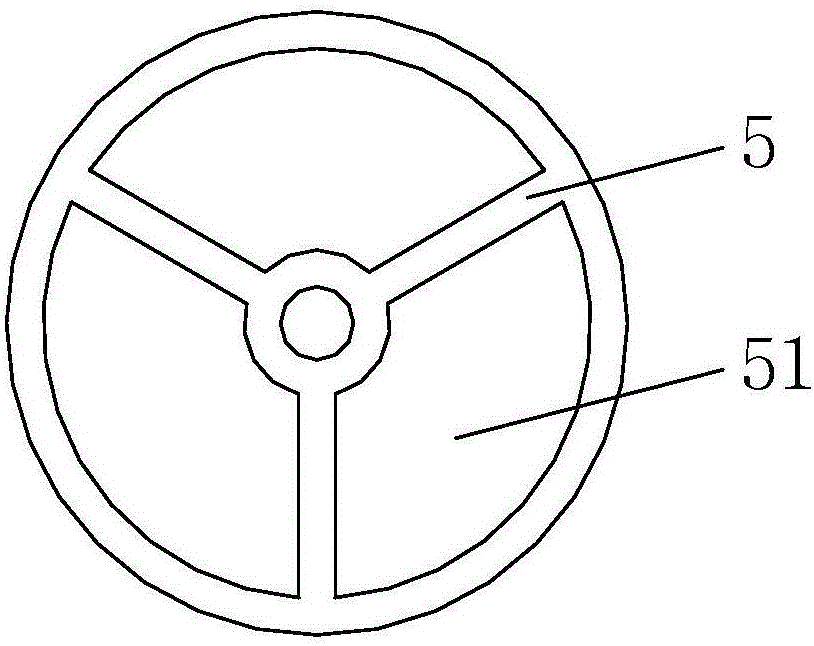
[0030] A magnetic induction pipeline generator, as attached figure 1 As shown, it includes a pipe 1 , a coil assembly, and a permanent magnet assembly. The coil assembly is located outside the inner wall of the pipe 1 , and the permanent magnet assembly is located inside the inner wall of the pipe 1 . Pipeline 1 is a non-conductive body, which can be a plastic part or the like. The coil assembly includes a coil 2, and the coil 2 can be wrapped circumferentially on the outer wall of the pipeline 1, or can be wrapped circumferentially and embedded in the wall of the pipeline 1, so that the coil 2 and the pipeline 1 are combined into one. The permanent magnet assembly comprises a permanent magnet 3, a shaft 4, a fixed bracket 5, a turbine 6, and the shaft 4 passes through the turbine 6 and the permanent magnet 3 and is fixed with both, and the fixed bracket 5 is as attached figure 2 As shown, it is a spoke-disc structure with a flow hole 51, the fixed bracket 5 is radially fixe...
Embodiment 2
[0035] The difference from Example 1 is that the positions of the coil and the permanent magnet are interchanged, that is, the coil assembly includes a coil, a shaft, a fixed bracket, and a turbine, the coil is closed and solidified, the contacts are explosion-proof, and the permanent magnet assembly includes a permanent magnet. The permanent magnet assembly is located outside the inner wall of the pipeline, and the coil assembly is located inside the inner wall of the pipeline.
[0036] The fluid flows in the pipeline, acting on the turbine to drive the turbine to rotate, and the shaft fixedly connected with the turbine drives the coil to rotate together, so that the permanent magnet cuts the magnetic induction line relative to the coil to generate current. The current generated by the coil inside the pipeline needs to be led out of the pipeline through the opening of the pipeline wall with wires, and the opening on the wall surface is sealed with epoxy resin.
Embodiment 3
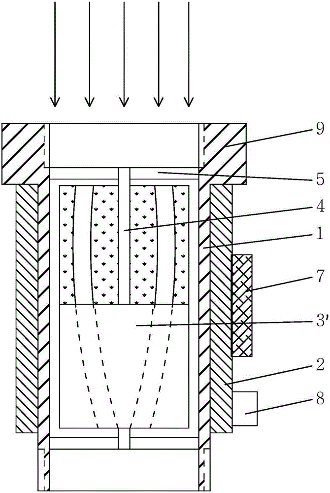
[0038] A magnetic induction pipeline generator, as attached image 3 As shown, it includes a pipe 1 , a coil assembly, and a permanent magnet assembly. The coil assembly is located outside the inner wall of the pipe 1 , and the permanent magnet assembly is located inside the inner wall of the pipe 1 . Pipeline 1 is a non-conductive body, which can be a plastic part or the like. The coil assembly includes a coil 2, and the coil 2 can be wrapped circumferentially on the outer wall of the pipeline 1, or can be wrapped circumferentially and embedded in the wall of the pipeline 1, so that the coil 2 and the pipeline 1 are combined into one. The permanent magnet assembly includes a permanent magnet 3', a shaft 4, and a fixed bracket 5. The shaft 4 passes through the permanent magnet 3' and is fixed thereto. The fixed bracket 5 is as attached figure 2As shown, it is a spoke-disc structure with a flow hole 51, the fixed bracket 5 is radially fixed to the inner wall of the pipeline 1...
PUM
 Abstract
Description
Claims
Application Information
 - R&D
- Intellectual Property
- Life Sciences
- Materials
- Tech Scout
- Unparalleled Data Quality
- Higher Quality Content
- 60% Fewer Hallucinations
Browse by: Latest US Patents, China's latest patents, Technical Efficacy Thesaurus, Application Domain, Technology Topic, Popular Technical Reports.
© 2025 PatSnap. All rights reserved.Legal|Privacy policy|Modern Slavery Act Transparency Statement|Sitemap|About US| Contact US: help@patsnap.com