
Microfluid-controlled frequency adjustable microstrip patch antenna

A microstrip patch antenna and microfluidic technology, applied in the field of communication, can solve problems such as electrical breakdown, nonlinearity, and power loss, and achieve the effect of increasing the effective dielectric constant

Inactive Publication Date: 2017-06-30
NANTONG UNIVERSITY +1
View PDF3 Cites 4 Cited by
  • Summary
  • Abstract
  • Description
  • Claims
  • Application Information

AI Technical Summary

Problems solved by technology

However, these methods all require bias voltage or current to change electrical parameters or electrical properties. This active circuit introduced to achieve adjustable frequency will not only cause power loss, but also bring nonlinearity and generate new frequency components. , and electrical breakdown may occur, which limits its application in high-power antennas
In addition, the introduction of the bias circuit also increases the complexity of the system

Method used


Image

  • Microfluid-controlled frequency adjustable microstrip patch antenna
  • Microfluid-controlled frequency adjustable microstrip patch antenna
  • Microfluid-controlled frequency adjustable microstrip patch antenna

Examples


Embodiment Construction

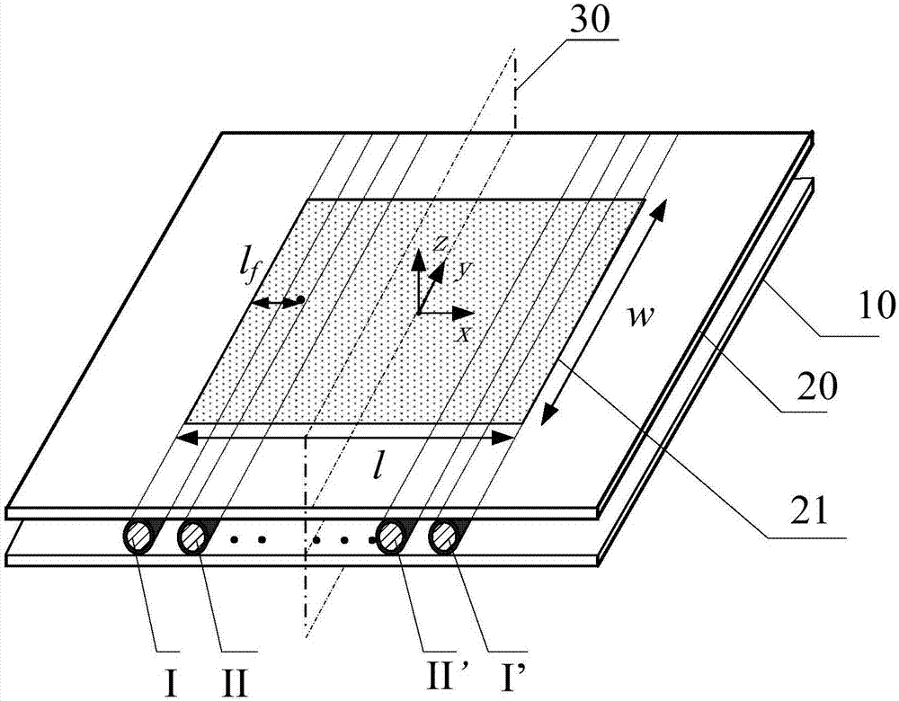
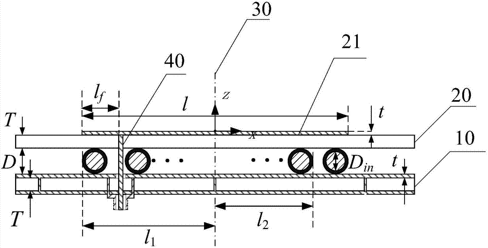
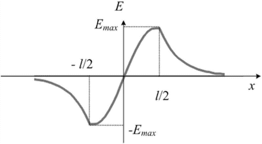
[0019] In the embodiment of the present invention, the antenna includes two facing substrates and a microfluidic channel into which microfluids can be injected, wherein a radiation unit in the form of a patch is arranged on one of the substrates, and the copper clad on the other substrate serves as a reflective ground. The feeding structure passes through the two substrates vertically and feeds the radiation unit, the microfluidic channel is arranged between the two substrates and is located in the electric field distribution area corresponding to the radiating unit, and the microfluidic channel and the feeding unit The mid-section plane of the radiating element where the electrical structure is located is vertical. Based on this structure, when microfluid is injected into the microfluidic channel, the effective dielectric constant between the radiation unit and the reflective ground can be affected. By setting the position of the microfluidic channel in the electric field dist...


PUM


Abstract

The invention relates to a microfluid-controlled frequency adjustable microstrip patch antenna. The antenna comprises two oppositely-disposed substrates and microfluid channels into which a microfluid can be injected; one of the substrates is provided with a radiating unit in the form of a patch; clad copper arranged on the other substrate is adopted as reflection ground; a feed structure vertically passes through the two substrates and feeds electricity to the radiation unit; and the microfluid channels are arranged between the two substrates and are located in an electric field distribution area corresponding to the radiating unit; and the microfluid channels are perpendicular to the centering surface of the radiating unit where the feed structure is located. According to the microfluid-controlled frequency adjustable microstrip patch antenna of the invention, the microfluid is injected into the microfluid channels, so that an effective dielectric constant between the radiating unit and the reflection ground can be increased, and therefore, the operating frequency of the antenna can be adjusted so as to be lowered; and the adjustable frequency range of the antenna can be controlled through loading the locations of the microfluid channels; and the reversibility of such adjustment can be realized through exhausting the microfluid channels. According to the microfluid-controlled frequency adjustable microstrip patch antenna, the adjustability of the frequency of the antenna can be realized safely and effectively at low cost, and the size of the antenna is not increased, and the integrity of the patch of the antenna is not damaged.

Description

technical field [0001] The invention relates to the communication field, in particular to a frequency-tunable microstrip patch antenna controlled by microfluidics. Background technique [0002] With the rapid development of wireless communication technology, the new generation of wireless communication urgently needs frequency reconfigurable devices, so that the system has the ability to work in multiple frequency bands. Correspondingly, the development of tunable antennas has attracted extensive attention, and many existing technologies can obtain the tunable performance of antennas, such as tunable designs using liquid metal, semiconductor diodes, or microelectromechanical system (MEMS) switches. report. Microstrip patch antenna is a widely used antenna, which can be used in modern wireless communication systems, and has the advantages of low profile, light weight and low cost. In traditional adjustable microstrip patch antennas, semiconductor varactor diodes or switches...

Claims


Application Information

Patent Timeline
IPC IPC(8): H01Q1/38H01Q1/50H01Q13/08
CPCH01Q1/38H01Q1/50H01Q13/08
Inventor 陈建新唐慧王志亮黄静李文华章国安
Owner NANTONG UNIVERSITY
Learn More