Coupled inductor quasi-Z-source DC-DC converter

A technology of DC-DC and coupled inductance, applied in the direction of adjusting electrical variables, converting DC power input to DC power output, instruments, etc., can solve problems such as unachievable, difficult to meet, gain limitation, etc., and achieve a wide range of application prospects , The effect of continuous input current

Inactive Publication Date: 2016-07-13
SOUTH CHINA UNIV OF TECH
View PDF2 Cites 3 Cited by
  • Summary
  • Abstract
  • Description
  • Claims
  • Application Information

AI Technical Summary

Problems solved by technology

However, many step-up DC / DC converters are limited by the duty cycle, parasitic parameters and losses, and cannot achieve a large boost. For example, the flyback converter has a voltage gain of nD / (1-D), where n is the transformer Turn ratio, D is the duty cycle, but due to the influence of parasitic parameters, its gain is limited; another example is the quasi-Z source converter, its voltage gain is 1 / (1-2D), which has a certain improvement compared with the Boost converter , but it is still difficult to meet the needs of practical applications

Method used


Image

  • Coupled inductor quasi-Z-source DC-DC converter
  • Coupled inductor quasi-Z-source DC-DC converter
  • Coupled inductor quasi-Z-source DC-DC converter

Examples


Embodiment Construction

[0011] The present invention will be described in further detail below in conjunction with the embodiments and accompanying drawings, but the embodiments of the present invention are not limited thereto. It should be noted that, if there are any processes or parameters that are not specifically described in detail below, those skilled in the art can understand or implement them with reference to the prior art.

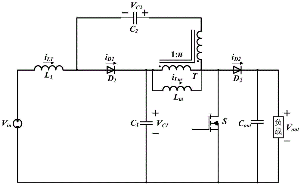
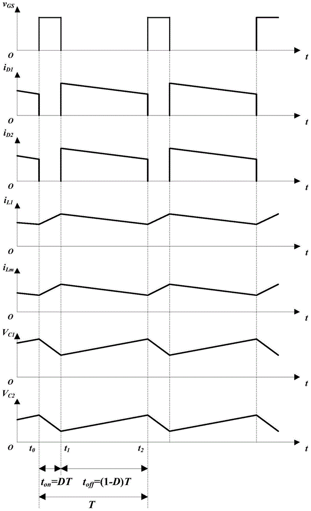
[0012] The basic topological structure of the present invention and the voltage and current reference direction of each main component are as follows: figure 1 shown. For the convenience of verification, the devices in the circuit structure are regarded as ideal devices. The drive signal v of the switch tube S GS , the first diode D 1 current i D1 , the second diode D 2 current i D2 , the first inductance L 1 current i L1 , The magnetizing inductance L of the transformer T m current i Lm , the first capacitance C 1 Voltage V C1 , the second capacitance C 2...


PUM


Abstract

The present invention provides a coupled inductor quasi-Z-source DC-DC converter. The converter comprises a direct current input power supply, a first inductor (L1), a first diode (D1), a first capacitor (C1), a second capacitor (C2), a transformer with a turn ratio of 1:n, a switch tube (S), a second diode (D2), an output capacitor (Cout) and a load. Compared with a flyback converter, the quasi-Z-source converter has high voltage gain and is suitable for the occasion of non-isolated high gain direct voltage transformation.

Description

technical field [0001] The invention relates to the field of DC / DC converters, in particular to a coupled inductance quasi-Z source DC-DC converter. Background technique [0002] In recent years, photovoltaic power generation technology has achieved unprecedented development, and it has also become one of the main utilization methods of solar energy. Photovoltaic grid-connected power generation technology is of great significance to alleviate the energy crisis, protect the environment and ensure sustainable economic development. Usually, the output voltage of the photovoltaic array battery is low, and it must be boosted by a DC / DC converter to meet the requirements of the grid-connected inverter, so the DC / DC converter is required to have higher gain and efficiency. However, many step-up DC / DC converters are limited by the duty cycle, parasitic parameters and losses, and cannot achieve a large boost. For example, the flyback converter has a voltage gain of nD / (1-D), where n...

Claims


Application Information

Patent Timeline
Patent Type & Authority Applications(China)
IPC IPC(8): H02M3/155H02M1/32
CPCH02M1/32H02M3/155H02M3/1552
Inventor 张波沈瀚云罗安
Owner SOUTH CHINA UNIV OF TECH
Why Eureka
Try Eureka