Drive system of high-pressure fuel pump, high-pressure fuel pump assembly and internal combustion engine

A driving system and high-pressure pump technology, applied in liquid fuel engines, charging systems, fuel injection pumps, etc., can solve the problems of high cost, high fuel consumption, high weight, etc. glitch effect

Inactive Publication Date: 2016-07-13
BAYERISCHE MOTOREN WERKE AG
View PDF17 Cites 3 Cited by
  • Summary
  • Abstract
  • Description
  • Claims
  • Application Information

AI Technical Summary

Problems solved by technology

This in turn leads to a higher weight and higher cost of the drive system of such a fuel high pressure pump
In addition, higher fuel consumption occurs because this type of drive of the fuel high-pressure pump is associated with higher frictional power

Method used


Image

  • Drive system of high-pressure fuel pump, high-pressure fuel pump assembly and internal combustion engine
  • Drive system of high-pressure fuel pump, high-pressure fuel pump assembly and internal combustion engine
  • Drive system of high-pressure fuel pump, high-pressure fuel pump assembly and internal combustion engine

Examples


Embodiment Construction

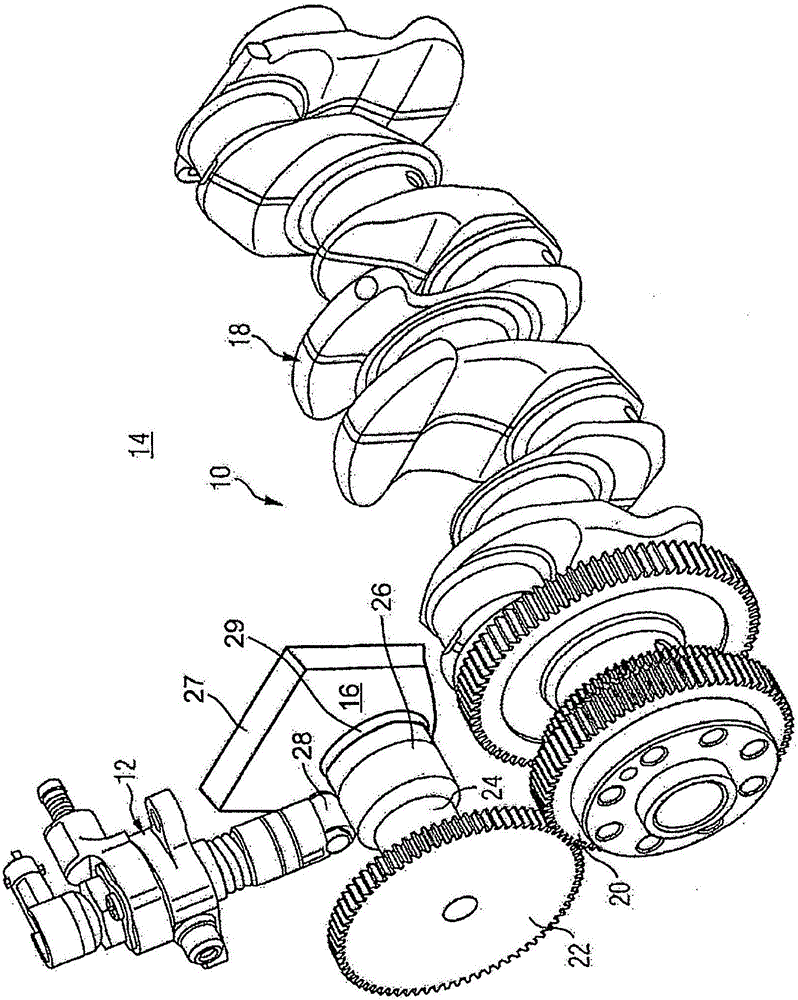
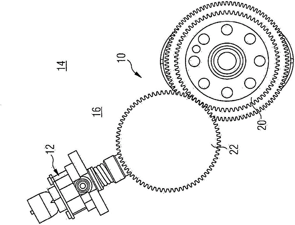
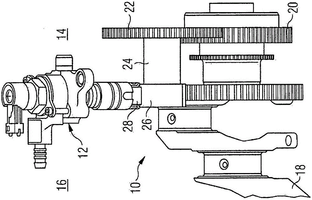
[0051] figure 1 A first exemplary embodiment of a drive system 10 according to the invention of a high-pressure fuel pump 12 of an internal combustion engine 14 which is installed in a high-pressure fuel pump assembly 16 according to the invention is shown.

[0052] exist figure 1 The high-pressure fuel pump assembly 16 shown in is installed in the internal combustion engine 14 according to the invention.

[0053] The drive system 10 has the shown drive train, which is coupled on the drive side to a crankshaft 18 and on the output side to a camshaft, not shown in detail here, for the control valves.

[0054] exist figure 1 In the embodiment shown, the internal combustion engine 14 is a diesel engine with common rail technology, and the high-pressure fuel pump 12 is arranged upstream of a so-called rail or high-pressure accumulator on the input side.

[0055] The crankshaft 18 of the internal combustion engine 14 is provided with a crank gear 20 on the end side. The cranksh...


PUM


Abstract

The invention relates to a drive system (10) of a high-pressure fuel pump (12) of an internal combustion engine (14). The system comprises a drive train which is coupled on the input side to a crankshaft (18) and on the output side to a valve-controlling camshaft. The system also comprises at least one drive-system cam (26) driving the high-pressure fuel pump (12) directly and situated in the drive train at a distance from the valve-controlling camshaft. The drive system has no chain and no toothed belt for driving the drive-system cam. The invention also relates to a high-pressure fuel pump assembly and to an internal combustion engine.

Description

technical field [0001] The invention relates to a driving system of a fuel high-pressure pump, a fuel high-pressure pump assembly and an internal combustion engine. Background technique [0002] High-pressure fuel pumps are known from the prior art. [0003] High-pressure fuel pumps of this type are used, for example, in common-rail diesel engines to pump fuel into a high-pressure accumulator. [0004] A known high-pressure fuel pump of an internal combustion engine for supplying fuel can, for example, be screwed with its housing to the crankcase of the internal combustion engine. The drive can be via a chain or a toothed belt, which drives the intermediate shaft. This intermediate shaft is then coupled to a separate shaft located in the interior of the pump housing, which in turn has a drive system cam that drives a tappet of the high-pressure pump. Such high-pressure fuel pumps are also referred to as so-called "stand-alone" high-pressure fuel pumps. It has proven to b...

Claims


Application Information

Patent Timeline
Patent Type & Authority Applications(China)
IPC IPC(8): F02M59/44
CPCF02M59/44F02M63/0265F02M59/027F02M39/02F02M59/06F02B67/04F04B53/006F04B17/05F02M59/102
Inventor T·米特劳尔W·巴尔特F·柯尼希斯马克
Owner BAYERISCHE MOTOREN WERKE AG
Why Eureka
Try Eureka