
A posterior fixation plate for acetabular anterior and posterior column fractures

A technology for fixing steel plates and anterior and posterior columns, applied in the direction of fixator, outer plate, internal bone synthesis, etc., can solve the problems of difficult operation, high blood loss, long incision, etc., and achieves reduced surgical difficulty, less blood loss, and surgical incision. small effect

Inactive Publication Date: 2018-01-12
王钢
View PDF11 Cites 0 Cited by
  • Summary
  • Abstract
  • Description
  • Claims
  • Application Information

AI Technical Summary

Problems solved by technology

[0004] Although the above combined plate can fix the anterior and posterior meridians of the acetabulum at the same time, it also has the following disadvantages: since the combined plate is fixed on the proximal arcuate surface of the iliac fossa, both the lag screw and the fixation screw must be inserted from the front of the iliac fossa. , so the joint plate can only be placed through the front surgical approach
The anatomical position of the acetabulum is relatively deep, and the adjacent anatomical relationship is complicated. The anterior surgical channel needs to pass through the pelvic cavity. Due to the obstruction of the internal organs in the pelvic cavity, the operation is difficult, the incision is long, the exposure is wide, the amount of bleeding is large, and the operation is easy to be injured. And the organs in the pelvic cavity, there are many postoperative complications, such as iatrogenic sciatic nerve injury, heterotopic ossification, femoral head necrosis, etc.

Method used


Image

  • A posterior fixation plate for acetabular anterior and posterior column fractures
  • A posterior fixation plate for acetabular anterior and posterior column fractures
  • A posterior fixation plate for acetabular anterior and posterior column fractures

Examples


Embodiment Construction

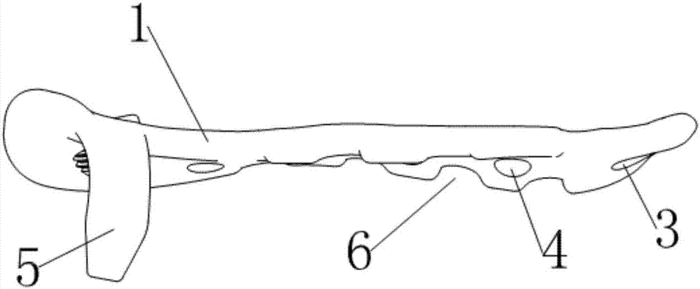
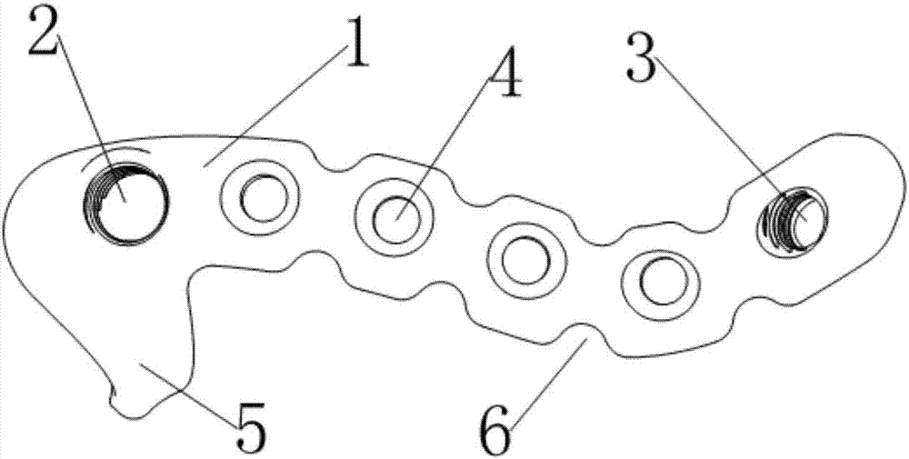
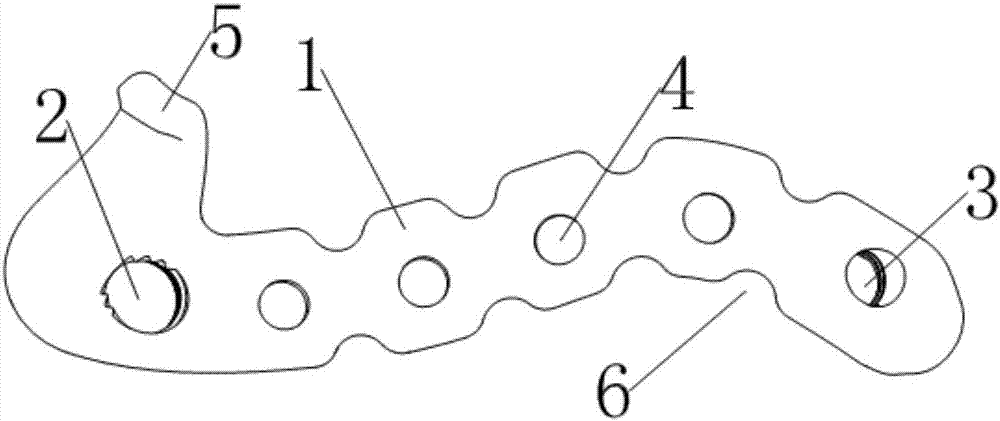
[0026] see Figure 1~5 , the rear road fixing steel plate in this example is made up of plate body 1, front column threaded hole 2, rear column threaded hole 3, fixing screw hole 4 and limit hook 5 that are located on plate body 1. The steel plate is made of titanium alloy, and the thickness of the plate body 1 is 3mm.

[0027] see Image 6 , and combined with Figure 1~5 , when in use, the plate body 1 is attached to the posterior wall of the acetabular column 8, its upper end is close to the top of the apex of the greater sciatic notch 7, and it is close to the posterior wall of the posterior column of the acetabulum 8, close to and along the acetabulum The inner edge of the posterior column extends to the root of the ischial spine 10 , and then bends along the lesser ischial notch 11 to extend below the top of the ischial tuberosity 12 . The curved surface formed by the lower surface of the plate body 1 matches the surface of the posterior wall 8 of the posterior acetabu...


PUM


Abstract

The invention relates to a posterior fixation plate for acetabular anterior and posterior column fractures. The posterior fixation plate has a plate body covering the posterior wall of the posterior column of the acetabulum; Close down and extend along the medial edge of the posterior column of the acetabulum to the root of the ischial spine, and then bend and extend to the lower part of the top of the ischial tubercle; the end of the plate body at the top of the greater sciatic notch is provided with a guide sleeve for connecting. Anterior column threaded hole, the axis of the anterior column threaded hole points to the anterior column of the acetabulum through the bone between the acetabular fossa and the square area, and the other end of the ischial tuberosity is provided with a posterior column threaded hole for connecting the guide sleeve, The axis of the posterior column threaded hole points to the caudal end of the ischial tuberosity through the bone in the ischial tuberosity; a number of fixing screw holes arranged along the plate body are arranged between the anterior column threaded hole and the posterior column threaded hole; One end of the plate body corresponding to the threaded hole of the front column is provided with a limit hook hooked on the upper part of the greater sciatic notch.

Description

technical field [0001] The invention relates to a surgical instrument, in particular to a fixed steel plate for the acetabular and surrounding structures, which is suitable for fixing fractures of the anterior and posterior columns of the acetabulum in posterior operations. Background technique [0002] The acetabulum and its surrounding structures can be divided into an anterior column and a posterior column. The anterior column runs obliquely from the top of the iliac crest to the pubic symphysis through the pubic ramus, and is composed of part of the ilium and the pubic bone. The posterior column is formed by the greater sciatic notch via the From the center of the acetabulum to the ischial tuberosity, including the vertical part of the ischium and part of the ilium connected to the ischium; the anterior and posterior columns are in an inverted "Y" shape, hugging the acetabulum like a cradle, and meet on the medial side in the square area, preventing hip The joint is disp...

Claims


Application Information

Patent Timeline
Patent Type & Authority Patents(China)
IPC IPC(8): A61B17/80
CPCA61B17/8033A61B2017/564
Inventor 王钢张立峰汪祎然曹生鲁
Owner 王钢
Learn More