A flue gas purification device and method combining fluidized atomization and liquid film washing

A combined device and flue gas purification technology, which is applied in the field of flue gas purification, can solve the problems of difficulty in achieving a high level of desulfurization and dust removal efficiency, small momentum transfer, high flow pressure drop, etc., to achieve improved stability and load adaptability, Effects of size reduction such as height, reduction of head and power consumption

Active Publication Date: 2019-03-15
INST OF PROCESS ENG CHINESE ACAD OF SCI
View PDF11 Cites 0 Cited by
  • Summary
  • Abstract
  • Description
  • Claims
  • Application Information

AI Technical Summary

Problems solved by technology

The main disadvantages of the traditional spray desulfurization dust collector are: the spray water can only be fully atomized to ensure the efficiency of gas-liquid mass transfer, which requires special wear-resistant nozzles and high flow pressure drop, high power consumption and maintenance costs
Although the spray water and flue gas flow in opposite directions, since the water flow and the air flow are combined into streams with the least flow resistance and the flow routes are selected by themselves, the flow cross-sectional size of the average water stream and air stream is relatively large. Momentum transfer is small, the contact area and contact time per unit mass of smoke and water are small, and the mass transfer is poor
The main disadvantages of the traditional liquid film desulfurization dust collector are: the flow section of the flue gas passing through the liquid film is relatively large, the flue gas mostly passes through the water layer in the form of bubbling, and the contact area and contact time per unit mass of smoke and water are very small. Small
Although the use of a Venturi tube can also enhance the atomization of water and the mass transfer with flue gas, it is still difficult to achieve a high level of desulfurization and dust removal efficiency
As the capacity increases, the diameter of the Venturi tube increases, and the flue gas purification efficiency also decreases significantly.

Method used


Image

  • A flue gas purification device and method combining fluidized atomization and liquid film washing

Examples


Embodiment Construction

[0045] The following are examples of the present invention, which are only used for explanation of the application and not for limitation.

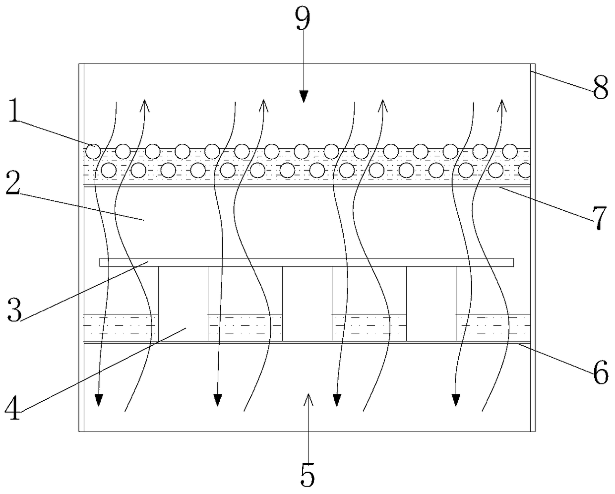
[0046] see figure 1 , a flue gas purification device combined with fluidized atomization and liquid film washing, the purification device 8 includes a gas distribution net 6 located at the lower part and a liquid distribution net 7 located at the upper part, and the gas distribution net 6 and the liquid distribution net 7 are arranged on With mesh holes, the purified liquid 9 can be separated into fine liquid streams through the liquid distribution network 7 and fall into the fluidized atomization layer, and then leave through the air distribution network 6; The atomization layer is then passed through the liquid distribution net 7 and the liquid film layer above to leave.

[0047] The flue gas and the purification liquid adopt counter-flow mass flow, and the flue gas passes through the lower gas distribution network, the upper liquid di...


PUM


Abstract

The invention discloses a fluidization atomization-liquid film washing combined flue gas purifying device. The device comprises a gas distribution screen located at a lower part and a liquid distribution screen located at an upper part, wherein the gas distribution mesh and the liquid distribution mesh are both provided with meshes; purifying liquid can be separated into fine liquid flows by the liquid distribution screen, falls into a fluidization atomization layer and passes through the gas distribution screen to leave the purifying device; and to-be-purified flue gas can uniformly enter the fluidization atomization layer through the gas distribution screen and then passes through the liquid distribution screen and a liquid film layer thereon to leave. The invention also discloses a method for removing dust in flue gas by using the device. A purifying liquid circulating pump of a purifying system matching with the device is greatly reduced in power consumption; and used equipment is simple in structure and easy to maintain.

Description

technical field [0001] The invention relates to the field of flue gas purification, in particular, the invention relates to a flue gas purification device and method combining fluidized atomization and liquid film washing. Background technique [0002] Traditional flue gas purification technologies include centrifugal separation dust removal technology, electric dust removal technology, bag dust removal technology and wet flue gas purification technology. [0003] The equipment structure of the centrifugal separation dust removal technology is simple, and the inertial separation effect can be improved by increasing the flue gas flow rate. However, due to the overall flow of the air flow, the large cross-sectional area of ​​the flow, and the long average stroke of the separation of solids from the gas, the air flow has secondary effects on the separated dust particles. Due to the influence of carryover, the separation of gas and solid is difficult to complete, not only the re...

Claims


Application Information

Patent Timeline
Patent Type & Authority Patents(China)
IPC IPC(8): B01D47/00B01D53/78B01D53/50B01D53/64
Inventor 郝江平房贤赵康何宁刘新华
Owner INST OF PROCESS ENG CHINESE ACAD OF SCI
Why Eureka
Try Eureka