Flanging machine

A flanging machine and flanging technology, applied in the field of flanging machines, can solve the problems of reduced work efficiency, unbalanced force on hydraulic cylinders, large effects of straps and pads, etc., so as to improve flanging efficiency and improve working efficiency. , to avoid difficult effects

Inactive Publication Date: 2016-07-20
TIANJIN JULONG HVAC EQUIP DEV
View PDF8 Cites 1 Cited by
  • Summary
  • Abstract
  • Description
  • Claims
  • Application Information

AI Technical Summary

Problems solved by technology

[0002] A large number of copper pipes are used in hydraulic system pipes on ships, and the connection between copper pipes and other stainless steel pipes can only be made through steel flanges. Due to the poor weldability between steel flanges and copper pipes, if you want The connection between the copper tube and the flange is not leaking. The best way is to flang one end of the copper tube, insert the steel flange from the other end of the copper tube, and fasten the two flanges with bolts to achieve The connection between the copper tube and the stainless steel tube; at present, some shipbuilding companies still use the relatively backward manual flanging process of the copper tube in the production process of the copper tube. This process has low production efficiency and poor molding quality, and often appears in purple Due to the perforation corrosion caused by the flanging defect at the flange of the copper pipe, the installed pipeline has to be reworked, which greatly increases the production cost and affects the production efficiency. Therefore, some shipbuilding enterprises have to use outsourcing The loose sleeve flange assembly is used to replace the flanging of the copper tube, which not only increases the welding workload of the copper tube, but also increases the production cost. According to the flanging machine published in Chinese patent 201320785967.6, the copper tube can be effectively turned over. , but the working efficiency of the single-acting hydraulic cylinder used in it is not only low, but also the force of the hydraulic cylinder is unbalanced, which has a greater effect on the band and the pad, which is easy to cause damage to the parts. At the same time, the tail of the copper pipe adopts a stopper The disadvantage of this is that it is inconvenient to install, and when the copper tube is flanged, the copper tube itself will undergo a certain longitudinal deformation, making it difficult to remove the copper tube from the flanging upper mold, thereby reducing work efficiency

Method used


Image

  • Flanging machine

Examples


Embodiment Construction

[0011] In order to make the objectives, technical solutions and advantages of the present invention clearer, the following further describes the present invention in detail with reference to the accompanying drawings and embodiments. It should be understood that the specific embodiments described herein are only used to explain the present invention, but not to limit the present invention.

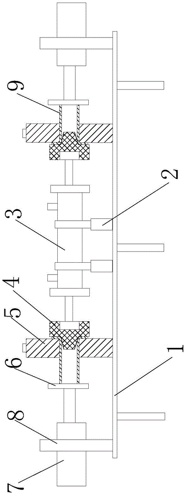
[0012] See figure 1 , A flanging machine, comprising a workbench 1 and a copper tube 9. The intermediate position of the workbench 1 is connected with a main hydraulic cylinder 3 through a fixing device 2, and the axis of the main hydraulic cylinder 3 is arranged parallel to the horizontal plane of the workbench 1. In this way, the flanging quality of the copper tube 9 can be guaranteed. The working table 1 is also provided with a flanging concave die 4 and a flanging upper die 5. The main hydraulic cylinder 3 is a double-acting hydraulic cylinder, which can simultaneously realize the flangi...


PUM


Abstract

The invention relates to a flanging machine. The flanging machine comprises a work table and copper pipes; the middle of the work table is connected to a main hydraulic cylinder through fixing devices; the work table is provided with female flanging dies and upper flanging dies, the main hydraulic cylinder is a double-action hydraulic cylinder, the two sides of the main hydraulic cylinder are connected to the female flanging dies, and the upper flanging dies are arranged on the two sides of the work table; the two sides of the work table are connected to auxiliary hydraulic cylinders through fixing sleeves, and baffles used for supporting the copper pipes are arranged at the ends of piston rods of the auxiliary hydraulic cylinders. The flanging machine is simple in structure and reasonable in design; a single-action hydraulic cylinder is changed into the double-action hydraulic cylinder, and therefore the copper pipes can be flanged easily, and the flanging efficiency of the copper pipes can be improved effectively; by arranging the auxiliary hydraulic cylinders, the copper pipes can be supported and can be fast taken out from the upper flanging dies after flanging of the copper pipes is completed.

Description

Technical field [0001] The invention relates to the technical field of mechanical manufacturing, in particular to a flanging machine. Background technique [0002] The hydraulic system piping on ships needs to use a lot of copper pipes. The connection between the copper pipes and other stainless steel pipes can only be done through steel flanges, and because the weldability of steel flanges and copper pipes is poor, it is necessary to make The connection between the copper pipe and the flange is not leaking. The best way is to turn one end of the copper pipe and insert the steel flange from the other end of the copper pipe, and then tighten the two flanges with bolts. The connection of copper pipes and stainless steel pipes; at present, some shipbuilding enterprises still use the backward manual flanging process of red copper pipes in the production process of red copper pipes. This process has low production efficiency and poor molding quality, and it often appears in purple cop...

Claims


Application Information

Patent Timeline
IPC IPC(8): B21D19/00
Inventor 李士奎李四海
Owner TIANJIN JULONG HVAC EQUIP DEV
Why Eureka
Try Eureka