Supercharge Your Innovation With Domain-Expert AI Agents!

A kind of method utilizing friction stir welding to prepare copper elastic belt

A technology of friction stir welding and copper elastic band, which is used in welding equipment, non-electric welding equipment, manufacturing tools, etc., can solve the problems of increased hardness of elastic band, stress concentration penetration cracks, and reduced strength of copper elastic band and steel matrix joint. , to increase the amount of charge, the joint strength is high, and the connection strength is guaranteed.

Active Publication Date: 2018-03-27
安徽万宇机械设备科技有限公司
View PDF10 Cites 0 Cited by
  • Summary
  • Abstract
  • Description
  • Claims
  • Application Information

AI Technical Summary

Problems solved by technology

[0003] The present invention solves the copper elastic belt prepared by the existing overlay welding method. When iron enters the copper alloy overlay welding layer, it will cause great stress concentration and serious penetration crack defects in the copper alloy overlay welding layer, so that the copper elastic belt and The joint strength of the steel matrix is ​​significantly reduced; not only that, but the pan-iron produced increases the hardness of the bullet belt sharply, and it is easy to scratch the rifling when the shell is fired, which shortens the service life of the gun bore. Methods

Method used


Image

  • A kind of method utilizing friction stir welding to prepare copper elastic belt
  • A kind of method utilizing friction stir welding to prepare copper elastic belt
  • A kind of method utilizing friction stir welding to prepare copper elastic belt

Examples


specific Embodiment approach 1

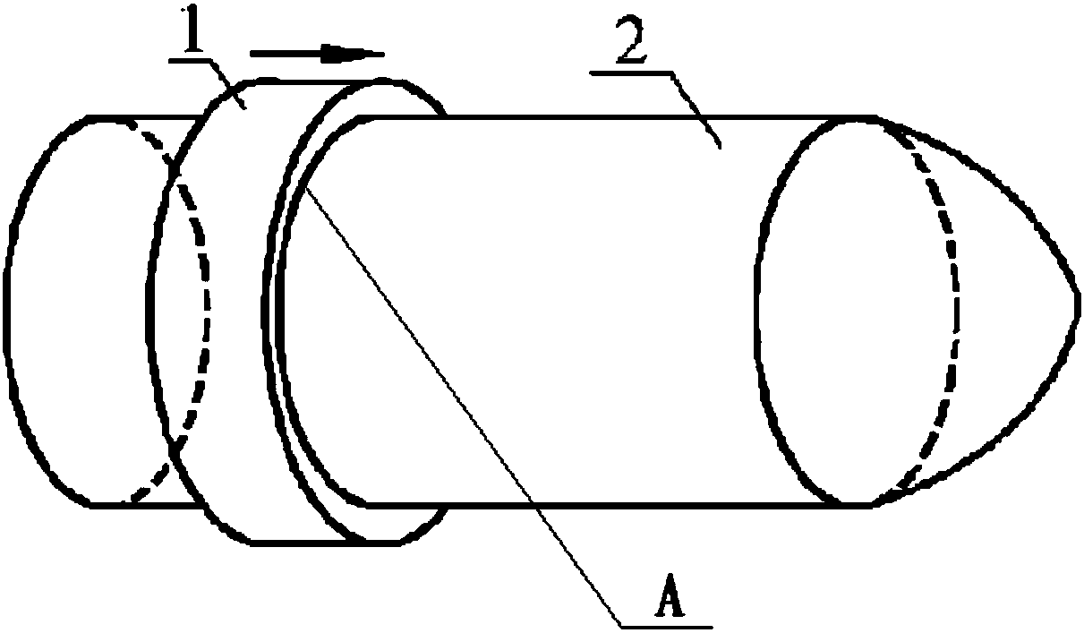
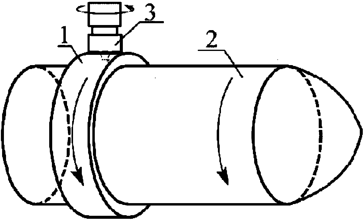
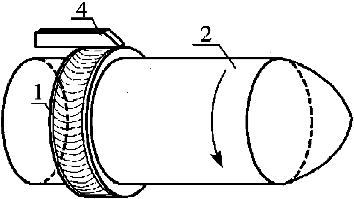
[0018] Specific implementation mode one: combine Figure 1 ~ Figure 3 Describe this implementation mode, this implementation mode is realized through the following steps:

[0019] Step 1, put the copper ring 1 on the shell shell 2, and move the copper ring 1 to the predetermined position A of the shell; it is also possible to open a radial groove at the predetermined position A on the shell shell 2, and place the copper ring 1 positioning and fixing in the radial groove;

[0020] Step 2: Use the tape winder to press the copper ring 1 to the shell shell 2 in the radial direction, tighten the copper ring 1 for subsequent welding, and clamp the shell shell 2 on the friction stir welding workbench with a clamp, At the same time, the copper ring 1 is clamped and fixed on the shell shell 2;

[0021] Step 3, welding: start the friction stir welding machine, the stirring head 3 is pressed into the copper ring 1, the shell shell 2 rotates along its own axis under the drive of the fix...

specific Embodiment approach 2

[0023] Specific implementation mode two: combination Figure 1 ~ Figure 3 This embodiment is described. In this embodiment, the shell casing 2 in step 1 is made of steel. Other steps are the same as in the first embodiment.

specific Embodiment approach 3

[0024] Specific implementation mode three: combination figure 2 Describe this embodiment. In this embodiment, the length of the stirring needle of the stirring head in step 3 is the same as the thickness of the copper ring 1 . Other steps are the same as those in Embodiment 1 or 2.


PUM


Abstract

The invention provides a method for preparing a copper bearing band through friction stir welding so as to solve the problem that according to a copper bearing band prepared through an existing build up welding method, because great stress concentration and severe permeation crack defects can be caused in a copper alloy build up welding layer when iron enters the copper alloy build up welding layer, the strength of a connector of the copper bearing band and a steel base body is remarkably lowered. The method includes the steps that firstly, the preset position A on a cannonball shell is sleeved with a copper ring; secondly, the copper ring is pressed towards the cannonball shell in the radial direction through a band collection machine, the copper ring is tightened, the cannonball shell is clamped on a friction stir welding workbench through a clamp, and meanwhile the copper ring is clamped on the cannonball shell; thirdly, welding is conducted, wherein a friction stir welding machine is started, a stirring head is pressed in the copper ring, the cannonball shell is driven by the clamp to rotate around the axis of itself, the copper ring also rotates, and welding is completed after the cannonball shell rotates by a circle; and fourthly, after welding is completed, repair welding is conducted on a keyhole through a filling type friction stir welding method, and preparation of the copper bearing band is completed at the moment. The method is used for preparing the copper bearing band.

Description

technical field [0001] The invention relates to a method for preparing a bullet belt in the shell manufacturing process, in particular to a method for preparing a copper bullet belt by friction stir welding. Background technique [0002] The belt is one of the main components of the shell, and it is widely used in shells of various sizes. Its main function is to seal the powder gas and make the shell rotate, while increasing the range, improving the accuracy, and reducing the wear of the rifling. The traditional method of producing the belt is the mechanical fitting method, which is to process the guide belt groove on the projectile body (the large-caliber shell is a dovetail groove), and roll the pattern on the bottom of the groove, so that the copper alloy or pure iron belt Fitted with the body under strong pressure. This traditional processing method not only takes a lot of time, but also causes serious wear on the tool. It also increases the wall of the shell, reduces t...

Claims


Application Information

Patent Timeline
Patent Type & Authority Patents(China)
IPC IPC(8): B23K20/12B23K103/22
CPCB23K20/122B23K2103/22
Inventor 万龙黄体方黄永宪吕宗亮
Owner 安徽万宇机械设备科技有限公司
Features
  • R&D
  • Intellectual Property
  • Life Sciences
  • Materials
  • Tech Scout
  • Unparalleled Data Quality
  • Higher Quality Content
  • 60% Fewer Hallucinations
Learn More