Ship-shaped amphibious car

An amphibious and ship-shaped technology, which is applied to amphibious vehicles, motor vehicles, transportation and packaging, and can solve problems such as loud noise, short voyage, and poor protection capabilities

Active Publication Date: 2016-07-20
刘持平
View PDF4 Cites 7 Cited by
  • Summary
  • Abstract
  • Description
  • Claims
  • Application Information

AI Technical Summary

Problems solved by technology

A vehicle that replaces amphibious vehicles is the hovercraft. The advantages of the hovercraft are high speed and can land on complex terrain. The disadvantages are large volume, poor protection ability, high energy consumption, short voyage, loud noise during navigation, and exposed propellers. Large radar reflection area is not conducive to stealth, poor stability, poor performance in complex sea conditions, high manufacturing cost and high use cost, so hovercraft is not an ideal landing combat tool

Method used


Image

  • Ship-shaped amphibious car
  • Ship-shaped amphibious car
  • Ship-shaped amphibious car

Examples


Embodiment 1

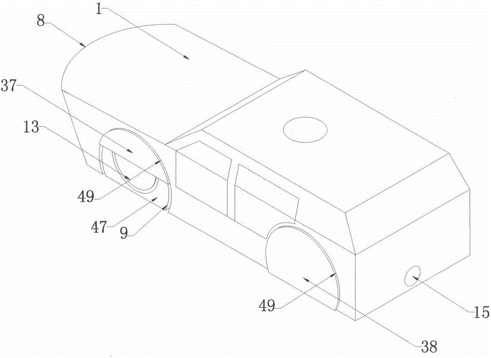
[0067] Such as figure 1 The shown upper cover plate fairing device 37 and the full cover plate fairing device 38 are fixed on the outer surface 49 of the pan arch, and there is a gap between the wheel arch outer surface 47 and the upper cover plate fairing device 37. When the cylindrical surface fairing device 9 rotates It does not interfere with the upper cover fairing device 37.

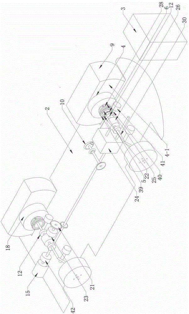
[0068] Such as image 3 As shown, the hollow transmission shaft device 6 passes through the hollow shaft device 5, Figure 4 The shown hollow transmission shaft driving gear device 29 is connected to the steering driven gear device 19, and the steering driven gear device 19 is connected to the universal joint device 27, and the universal joint device 27 is connected to the screw nut steering device 10, and the screw nut steering device 10 is connected to the steering joint Device 7, the transmission shaft of the steering driven gear device 19 can be selected to be recessed inward to leave a spac...

Embodiment 2

[0072] Such as Figure 6 As shown, the cylindrical surface stepped shaft seat device 54 on the center opening arch and the cavity type center opening arch lower cylindrical surface stepped hollow shaft seat device 55 are combined into a shaft sleeve, and one end of the hollow shaft device 56 passes through the shaft sleeve hole and uses a snap ring device 80 hinges are connected to the boat-shaped car body, and the other end of the hollow shaft device 56 is fixedly connected to the cylindrical stepped hollow shaft rotating chassis device 53; the speed regulating motor 58 is connected to the transmission shaft device 78, Figure 7 The transmission shaft device 78 shown passes through the hollow shaft device 56 to connect the cardan shaft device 79, and the cardan shaft device 79 is connected to the wheel device 68; the motor-driven worm device 83 is connected to the worm device 81, and the worm device 81 is connected to the worm gear device 82; The device 82 is mounted on the h...

Embodiment 3

[0076] Such as Figure 10 As shown, in the 4X4 wheeled plug-in hybrid ship type amphibious vehicle, only the flexible pipe and flexible wire device 96 pass through the hollow shaft device 95, and no transmission shaft passes through the hollow shaft device 95. One end of the hollow shaft device 95 is fixed on the boat body 91, and the other end of the hollow shaft device 95 is hinged to the conical surface stepped hollow shaft rotating chassis device 94. Figure 9 The shown fuel oil generating device 93 and the steering-by-wire device are installed on the flat-bottomed ship bottom 92, Figure 9 , Figure 8 The shown wheel device 114, braking device 115, wheel side motor device 97, double wishbone independent suspension device 107 are installed on the conical surface stepped hollow shaft rotating chassis device 94, the pontoon device 116, the cylindrical surface anti-slip rib fairing device 99 It is fixed on the conical surface stepped hollow shaft rotating chassis device 94,...


PUM


Abstract

The invention discloses a ship-shaped amphibious car. The ship-shaped amphibious car comprises four car wheel devices (14), hollow shaft devices (5) and four sets of worm wheel devices (39), wherein the four car wheel devices (14) are installed on four cylindrical-surface step hollow shaft rotating chassis devices (4) correspondingly; the first ends of the hollow shaft devices (5) are connected with a ship-shaped car body (1) through hinges, and the second ends of the hollow shaft devices (5) are fixedly connected with the four cylindrical-surface step hollow shaft rotating chassis devices (4); and the four sets of worm wheel devices (39) are installed on the first ends, inside the car, of the four hollow shaft devices (5) correspondingly, and rotating and stroke positioning of the four cylindrical-surface step hollow shaft rotating chassis devices (4) are driven by four sets of worm devices and the four sets of worm wheel devices (39). During switching of amphibious modes, when the four cylindrical-surface step hollow shaft rotating chassis devices (4) are all rotated by 180 degrees and switched into the water mode, the four car wheel devices (14) are rotated to the position above the ship bottom, and four stream-line surfaces (45) are rotated to the flat-bottom ship bottom (2) to take part in stream-line ship-shaped car body simulation so that the sailing resistance can be reduced.

Description

technical field [0001] The invention relates to an amphibious vehicle capable of navigating on water and traveling on land. Background technique [0002] When the amphibious vehicle sails on the water, the eddy currents formed by the wheels or tracks in the water generate greater resistance, which limits the further improvement of the navigation speed. At present, there are three main ways to increase the navigation speed of the amphibious vehicle: the first is to shrink the wheel device upwards Reduce the eddy current resistance generated by the wheels, but after the wheels are lifted, there will be depressions at the wheel arch cutouts. It is easy to be damaged when driving on land, and the failure rate is high; the second method is to design a ship bottom without a cover plate to close the wheel arch cutout after the wheel device is retracted upwards. The lowest point of the wheel arch cutout is above the bottom of the ship. When gliding at high speed, the wheel arch cut...

Claims


Application Information

Patent Timeline
IPC IPC(8): B60F3/00
CPCB60F3/00B60F3/0015B60F3/0038
Inventor 刘持平
Owner 刘持平
Why Eureka
Try Eureka