Hydraulic press pump controlled hydraulic system with renewable power generation

A hydraulic system and hydraulic machine technology, applied in the direction of fluid pressure actuation system components, mechanical equipment, fluid pressure actuation devices, etc., can solve the problems of increasing system cooling power, high system power consumption, waste of energy, etc., to ensure dimensional accuracy , high flow accuracy and high control accuracy

Inactive Publication Date: 2016-07-20
沈阳重机重矿机械设备制造有限公司
View PDF8 Cites 3 Cited by
  • Summary
  • Abstract
  • Description
  • Claims
  • Application Information

AI Technical Summary

Problems solved by technology

However, this utility model still realizes the control of the hydraulic press through the rapid forging valve, which also belongs to the valve control system, and the main shortcomings of the valve control system are as follows: one is the high power consumption of the system, the energy utilization low rate
First of all, the displacement or pressure of the high-pressure oil at the pump port of the valve control system cannot be adjusted when the hydraulic press is working, so when the hydraulic press is working intermittently, a large amount of high-pressure oil is converted into heat energy through overflow and lost; The huge compression energy accumulated in the main working cylinder of the hydraulic machine and the high-pressure pipeline is discharged back to the oil tank through the pressure relief valve. In the process, all the accumulated compression energy is converted into heat to make the hydraulic oil heat up and release the impact vibration on the pipeline. , all generate harmful useless work; third, in the valve control system, the rising and falling speed of the hydraulic motorized beam is completely controlled by the opening of the hydraulic valve, and the pressure oil passes through the orifice from high to low, and a part The energy is converted into heat energy of the hydraulic oil, which wastes energy and heats up the system. As the oil temperature rises, the heat energy of the system will increase the cooling power of the system accordingly, and the energy consumption will increase the system cost.
The second is the strong shock and vibration of the system: when the energy released by the pressure relief valve releases the high-pressure energy, the liquid impacts the components connected to it, such as pipes, valve blocks, etc., which greatly reduces the life of each component of the system and increases the failure rate. The production efficiency is greatly reduced; although the above-mentioned utility model has reduced the impact vibration, the system impact vibration has not been completely eliminated
[0003] In addition, the pump control hydraulic system of the existing hydraulic machine can allow the compression of hydraulic oil to be used repeatedly. The pump control system releases the pressure through the pump. During the pressure relief process, the hydraulic pump switches to a motor that drives the main motor to rotate under the pressure oil. No load output, the pressure potential energy is partially absorbed by the motor to reduce the energy output of the motor, but some of it is still not fully utilized, and when the speed of the motor is greater than the synchronous speed of the motor, the motor is in a state of power generation, which is uncontrollable and is detrimental to the grid

Method used


Image

  • Hydraulic press pump controlled hydraulic system with renewable power generation

Examples


Embodiment Construction

[0022] The present invention will be described in detail below in conjunction with the accompanying drawings.

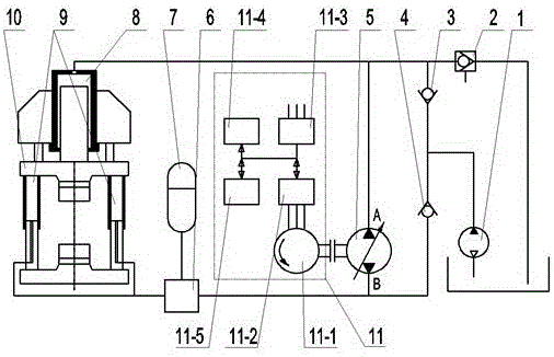
[0023] Such as figure 1 As shown, the technical scheme adopted in the present invention includes a hydraulic press 10, on which a main working cylinder 8 and a return cylinder 9 are arranged, and a two-way variable axial piston pump 5 is installed between the main working cylinder 8 and the return cylinder 9, and the two-way variable A pump return switching valve 6 and a return accumulator 7 are also installed between the axial plunger pump 5 and the return cylinder 9, the liquid discharge valve 2 is connected to the main working cylinder 8, and the liquid supply pump 1 is connected to the main working cylinder 8 through the first one-way valve 3. The main working cylinder 8 is connected, the liquid supply pump 1 is connected with the two-way variable axial piston pump 5 through the second check valve 4, and the main working cylinder 8 and the return cylinder 9 are d...


PUM


Abstract

The invention relates to a hydraulic press pump controlled hydraulic system with renewable power generation and aims at solving the problems of the traditional hydraulic press pump controlled hydraulic system of high power consumption, strong system impact vibration, high failure rate, low production efficiency and low energy utilization ratio without full utilization of compression energy. The hydraulic press pump controlled hydraulic system with renewable power generation is characterized in that a reversible variable axial plunger pump is installed between a main working cylinder and return cylinders; a liquid supply pump is connected with the main working cylinder through a first check valve and the reversible variable axial plunger pump through a second check valve and directly controls the main working cylinder and the return cylinders to drive a moving beam of a hydraulic press to move through the reversible variable axial plunger pump; and a regenerative power generation system is connected to the reversible variable axial plunger pump through a coupler. The hydraulic press pump controlled hydraulic system has the beneficial effects that the response speed of the system is rapid, the control accuracy is high, no impact vibration occurs in the pressure and charge relieving process of the main working cylinder, and thus impact vibration of the system is eliminated; and in addition, the compression energy of hydraulic oil of the hydraulic press can be converted to electric energy, or stored for recycling or directly supplied to other electric servo motors, so that the energy saving effect is remarkable.

Description

technical field [0001] The invention belongs to the technical field of hydraulic control, and in particular relates to a pump-controlled hydraulic system of a hydraulic machine capable of regenerative power generation with a regenerative power generation system. Background technique [0002] The hydraulic system equipped with the hydraulic press in the prior art is a valve control system. For example, the utility model with the application number 200820222400.7 discloses an "energy-saving rapid forging unit", which is also a hydraulic machine, including return hydraulic springs, rapid forging valves, Compressor beam, fast forging master cylinder, pressure detector, high-pressure main pump, stroke detector, frequency conversion liquid supply pump; return cylinder is directly connected to the compressor beam, so that the compressor beam returns and supports the press beam; frequency conversion liquid supply pump It is connected to the high-pressure main pump through pipelines,...

Claims


Application Information

Patent Timeline
Patent Type & Authority Applications(China)
IPC IPC(8): F15B11/17F15B1/04F15B21/14
CPCF15B1/04F15B11/17F15B21/14Y02E60/16
Inventor 元钢马影刘玉凤元靖云苏金玲赵飞蔺任志
Owner 沈阳重机重矿机械设备制造有限公司
Why Eureka
Try Eureka