Supercharge Your Innovation With Domain-Expert AI Agents!

Range Hood with Oil Separator

A range hood and oil-carrying technology, which is applied in the fields of oil fume removal, household heating, lighting and heating equipment, etc., can solve the problems of waste oil resources, greatly increased rotational resistance, motor burnout, etc., so as to reduce environmental protection pressure, The effect of promoting the full utilization of resources and prolonging the service life

Active Publication Date: 2018-03-06
YUEYANG ZHENGYUAN MACHINERY MFG CO LTD
View PDF7 Cites 0 Cited by
  • Summary
  • Abstract
  • Description
  • Claims
  • Application Information

AI Technical Summary

Problems solved by technology

[0003] 1. Waste precious oil resources and pollute the environment;
[0004] 2. The flue gas flow gradually cools down during the whole exhaust process. The fan is the end of the system with the lowest temperature and is prone to condensation or condensation. This is especially true in winter, resulting in a large increase in rotational resistance or motor burnout

Method used


Image

  • Range Hood with Oil Separator
  • Range Hood with Oil Separator
  • Range Hood with Oil Separator

Examples


Embodiment 1

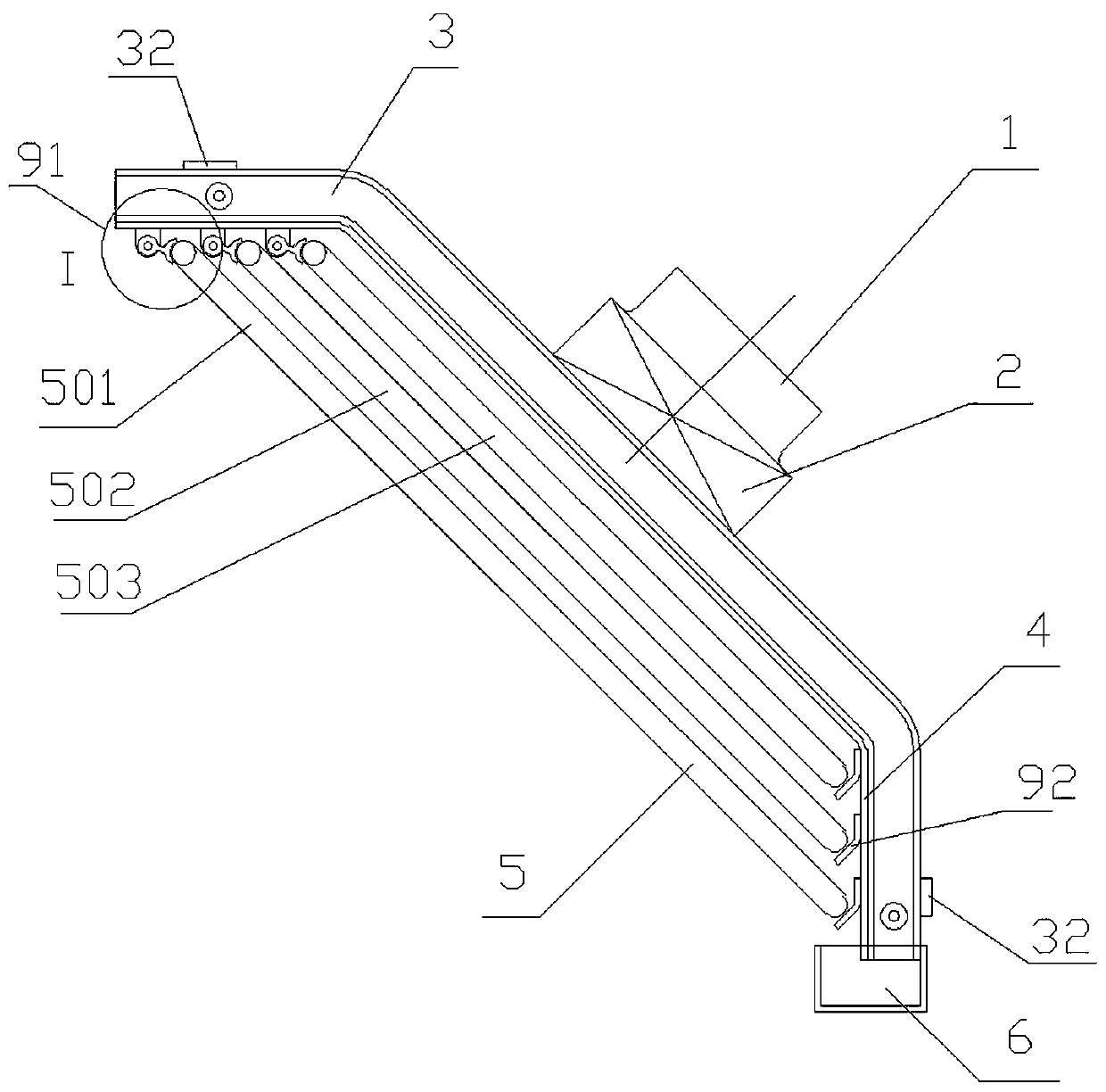
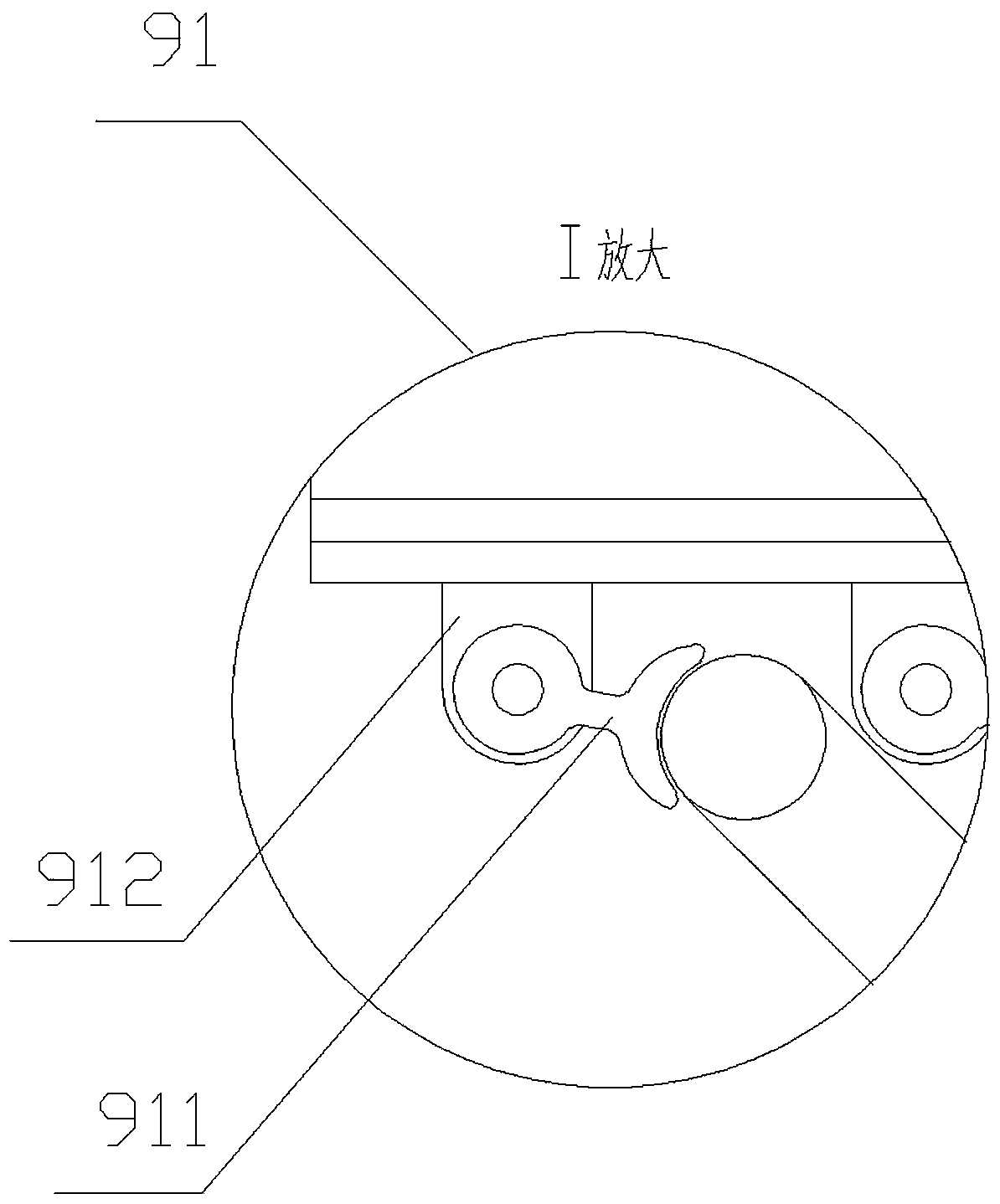
[0026] Such as figure 1 , 2 , 3, a range hood with oil separation, including exhaust pipe 1, blower fan 2, trough support 3, back plate 4, heat exchange oil trap 5, oil storage tank 6, cooling water switch 7 and temperature Control module 8, the groove bracket 3 is arranged at the left and right ends of the backboard 4, the air inlet of the fan 2 is arranged at the center position of the backboard 4, and the center position of the backboard 4 is set corresponding to the fan 2 The opening is used for fan 2 suction, the exhaust pipe 1 is arranged at the air outlet of the fan 2, the oil storage tank 6 is movably arranged at the bottom of the trough-shaped support 3, and the heat exchange oil catcher 5 passes through the upper The fixer 91 and the lower fixer 92 are installed on the upper and lower ends of the trough-shaped support 3, wherein: the heat exchange oil catcher 5 includes an oil catcher 51, a cooling water inlet 52, and a cooling water outlet 53, and all the oil catch...

Embodiment 2

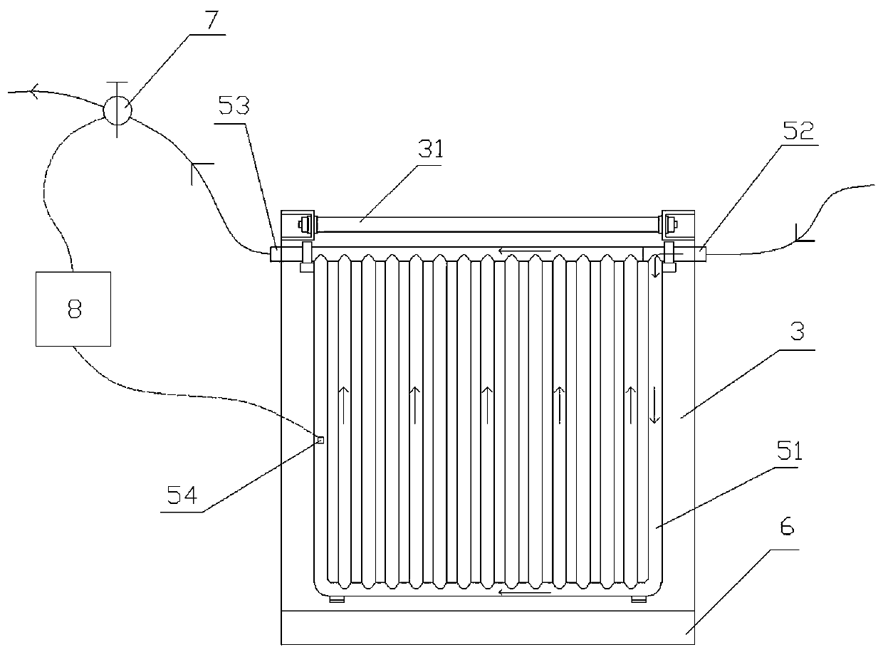
[0033] Such as image 3 As shown, compared with Embodiment 1, the range hood with oil separation described in this embodiment also includes a cooling water circulation driving device 10, and the cooling water inlet 52 and cooling water outlet 53 are respectively connected to the cooling water circulation driving device 10, The cooling water switch 7 is arranged between the cooling water outlet 53 and the cooling water circulation driving device 10 .

[0034] In this embodiment, the cooling water circulation driving device 10 includes a water pump 101 and a water tank 102 , and the water pump 101 is connected to and controlled by the temperature control module 8 .

[0035] The working principle of the present invention is: the exhaust gas produced by the cooking stove contains water vapor, oil vapor, carbide solid dust, etc., and the temperature is relatively high. After the cooler, it is rapidly cooled to about 20°C or lower to become a supersaturated gas mixture. Water and o...


PUM


Abstract

The invention discloses a range hood with an oil separation function.The range hood comprises an exhaust duct, a fan, a groove-shaped support, a backing plate, heat exchange oil traps, an oil storage tank, a cooling water switch and a temperature control module; the oil storage tank is movably arranged at the bottom of the groove-shaped support, the heat exchange oil traps are installed at the upper end and the lower end of the groove-shaped support through an upper fixator and a lower fixator respectively, the heat exchange oil traps comprise oil trapping tubes, the bottoms of the oil trapping tubes are communicated, the upper portions of two oil trapping tubes close to a cooling water inlet are cut off, the upper portions of other oil trapping tubes are communicated, a temperature sensor is arranged in one oil trapping tube, a cooling water outlet is connected with the cooling water switch, the temperature sensor and the cooling water switch are connected with the temperature control module, and the temperature control module controls on and off of the cooling water switch according to a signal of the temperature sensor.According to the range hood with the oil separation function, substances such as water and oil in flue gas can be recycled, and the service life of the fan can be prolonged.

Description

technical field [0001] The invention relates to the technical field of range hoods, in particular to a range hood with oil separation. Background technique [0002] Most of the range hoods used in the kitchen are actually kitchen ventilators, which only have a simple ventilation function. Some of the latest range hoods have a certain function of separating oil, and the principle is collision capture. Because the catch plate, fence, mesh plate, etc. are in contact with the oily fume airflow, there is a certain temperature difference between the channel and the airflow at the initial stage, which can separate the oil from the air. However, as the use time increases, there is basically no temperature difference or a small temperature difference between the channel and the airflow. At this time, the oil in the flue gas flow is basically not separated, but is directly discharged into the atmosphere through the fan. Use this range hood mainly to have following problems: [0003...

Claims


Application Information

Patent Timeline
Patent Type & Authority Patents(China)
IPC IPC(8): F24C15/20
CPCF24C15/20F24C15/2021
Inventor 徐飞刘丰冰任锦平
Owner YUEYANG ZHENGYUAN MACHINERY MFG CO LTD
Features
  • R&D
  • Intellectual Property
  • Life Sciences
  • Materials
  • Tech Scout
  • Unparalleled Data Quality
  • Higher Quality Content
  • 60% Fewer Hallucinations
Learn More