Novel cylindrical inner gear turning method

A gear car, cylinder technology, applied in the direction of belt/chain/gear, gear teeth, components with teeth, etc., can solve the problem of not being able to withstand cutting force, reducing gear bearing capacity, life and reliability, ring gear teeth, etc. problems such as low manufacturing precision, to achieve the effect of reducing the investment of machine tools, low cost of machine tools and tools, and high processing efficiency

Active Publication Date: 2016-07-27
宜昌长机科技有限责任公司
View PDF5 Cites 4 Cited by
  • Summary
  • Abstract
  • Description
  • Claims
  • Application Information

AI Technical Summary

Problems solved by technology

[0002] It can be seen from the mechanical principle and gear processing technology and principle that the involute of the internal gear tooth is an expansion curve in the base circle, and the fan Cheng method gear grinding process with high machining accuracy cannot be used to manufacture the internal gear teeth
At the same time, if the normally meshed external gear is used as the rolling gear, the existing rolling equipment cannot control the deformation uniformity of the tooth surface of the internal gear and the backlash of the meshing gear pair, so that the meshing accuracy required by the internal gear cannot be achieved. Has not been successfully implemented in internal gear tooth machining
[0003] In the prior art, internal gears are usually processed by forming methods such as gear shaping, tooth drawing, and forming milling. However, the manufacturing precision of the internal gear teeth processed by the above methods is low, generally not exceeding 7 grades, resulting in gears inside Vibration, noise, additional dynamic load, etc. are generated in the meshing transmission, which reduces the bearing capacity, life and reliability of the gear, and cannot meet the requirements of high-end equipment for precise transmission
[0004] At present, there are certain difficulties in the processing of involute internal teeth with small diameter, large modulus, and large helix angle. The use of gear shaper machining requires a special spiral guide rail, and the small-diameter tool sleeve cannot bear the load of the large-modulus gear. cutting force

Method used


Image

  • Novel cylindrical inner gear turning method
  • Novel cylindrical inner gear turning method
  • Novel cylindrical inner gear turning method

Examples


Embodiment Construction

[0020] The technical means adopted by the present invention to achieve the intended invention purpose are further described below in conjunction with the drawings and preferred embodiments of the present invention.

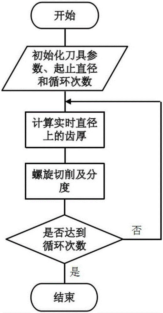
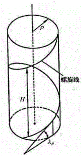
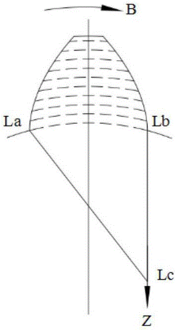
[0021] Such as Figure 1-2 , a new cylindrical gear turning method, which realizes the machining of involute tooth profile through the principle of plane multi-point NC forming method, which includes circumferential NC forming and radial NC forming. The workpiece axial linear axis Z-axis and the servo spindle B-axis are linked to complete the circular CNC forming action, and at the same time, the material removal in the tooth width direction is completed with a processing principle similar to slotting. The X-axis of the radial axis of the workpiece completes the radial numerical control forming of the plane multi-point numerical control forming method by numerical control. The multi-point compound motion of the Z-axis of the circular NC forming, the B-axis of the...


PUM


Abstract

A novel cylindrical inner gear turning method includes circumference numerical control forming and radial numerical control forming; a linear cutting shaft Z parallel to a workpiece shaft and a rotating servo shaft B of a workpiece are in linkage to achieve the method; by changing the positioning distance of the linear cutting shaft Z, the circumference numerical control forming is completed when the workpiece is rotated; circumferential feeding is achieved through the relative position of the linear movement of the shaft Z; during plane multi-point numerical control forming, the indexing of each one-point processed spiral line and teeth is achieved through the rotating servo shaft B, and meanwhile material removal in the tooth width direction is completed; a workpiece radial shaft X completes the radial numerical control forming of a plane multi-point numerical control forming method in a numerical control manner; and multi-point composite movement of the circumference numerical control forming shaft Z and the radial numerical control forming shaft X forms a plane involute. The novel cylindrical inner gear turning method is suitable for inner tooth machining of a small-diameter, large-modulus and large-spiral-angle involute, only a numerical control lathe and a machining program provided by the method are needed in machining, the machining efficiency is high, and the cost of a machine tool and a tool is low.

Description

technical field [0001] The invention relates to a novel cylindrical internal gear turning method, which is especially suitable for machining involute internal gears with small diameter, large modulus, and large helix angle. During processing, only a numerical control lathe and the processing program provided by the method are required, and the processing efficiency is high. Low machine and tool costs. Background technique [0002] It can be seen from the mechanical principle and gear processing technology and principle that the involute of the internal gear tooth is an expansion curve in the base circle, and the fan Cheng method gear grinding process with high machining accuracy cannot be used to manufacture the internal gear teeth. At the same time, if the normally meshed external gear is used as the rolling gear, the existing rolling equipment cannot control the deformation uniformity of the tooth surface of the internal gear and the backlash of the meshing gear pair, so t...

Claims


Application Information

Patent Timeline
Patent Type & Authority Applications(China)
IPC IPC(8): B23F17/00
CPCB23F17/003
Inventor 邓应诚付君健常月舟黄帅
Owner 宜昌长机科技有限责任公司
Why Eureka
Try Eureka