Automatic plate cutting device

An automatic cutting device and plate technology, which is applied in metal processing and other directions, can solve problems such as troublesome operation, reduce work efficiency and production cost, and shorten the service life of the device, so as to improve work efficiency, realize automation, and save working time.

Inactive Publication Date: 2016-07-27
SHANDONG JIANZHU UNIV
View PDF8 Cites 3 Cited by
  • Summary
  • Abstract
  • Description
  • Claims
  • Application Information

AI Technical Summary

Problems solved by technology

[0002] The current building construction will inevitably use plates of various shapes and sizes, and related cutting devices will inevitably be used. The current device can only cut materials with a fixed size and a single direction in a single job. It is very troublesome to operate the cutting area and cutting direction of the material. During the cutting process, the plate is easily affected by the tool and moves on the bracket, so that the cut product has an irregular shape and becomes a waste product, and the device needs to be close

Method used


Image

  • Automatic plate cutting device
  • Automatic plate cutting device

Examples


Example Embodiment

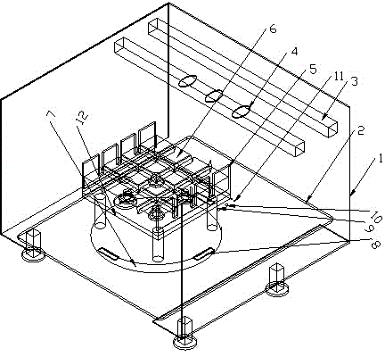
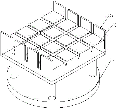
[0008] An automatic plate cutting device, consisting of a cutting machine housing 1, a conveyor belt 2, a tool holder 3, a cutting tool 4, a side clamping plate 5, a plate bracket 6, a rotating base 7, a signal receiver 8, and a tool working signal transmitter 9 , Rotation signal transmitter 10, tool work signal transmitter 11, gravity sensing device 12; It is characterized in that a series of grooves are evenly arranged on the contact surface of the plate bracket 6 and the material to be processed, and side clamping plates 5 are fixed on both sides. , A gravity sensing device 13 is installed inside the bracket. The bracket is fixedly connected to the rotating base 8 by a nut and installed on the conveyor belt 2. The edge of the rotating base 8 is equipped with four signal receivers, front and rear, left and right, and signal transmitters on the conveyor belt. Correspondingly, the four groups of cutting knives are respectively installed on two tool holders, and the tool holders ...


PUM


Abstract

An automatic plate cutting device is composed of a cutting machine shell, a conveying belt, cutting tools, tool stands, side clamping plates, a plate bracket, a rotating base, signal receivers, signal emitters and a gravity sensing device; grooves are evenly formed in the contact surfaces between the plate bracket and plates; the side clamping plates are installed at two sides of the plate bracket; a gravity sensor is arranged in the bracket; the gravity sensor is linked with the base through nuts; the gravity sensor and the base are installed on the conveying belt together; the four signal receivers are arranged in the front position, the back position, the left position and the right position of the side edge of the rotating base; the signal receivers correspond to the signal emitters on the conveying belt; the four groups of the cutting tools are installed on the two tool stands respectively; and the tool stands are fixed on the cutting device. Compared with the prior art, the signal sensing and the single chip microcomputer control are adopted, the number of the working cutting tools can be selected according to the demand, finished products of different sizes can be cut out, the grooves are reserved in the plate bracket, the plates can be cut out thoroughly when the bracket is not damaged, the gravity sensor is arranged in the bracket, and the reciprocating motion of the device can be achieved.

Description

technical field [0001] The invention relates to a plate automatic cutting device in the construction industry. Background technique [0002] The current building construction will inevitably use plates of various shapes and sizes, and related cutting devices will inevitably be used. The current device can only cut materials with a fixed size and a single direction in a single job. It is very troublesome to operate the cutting area and cutting direction of the material. During the cutting process, the plate is easily affected by the tool and moves on the bracket, so that the cut product has an irregular shape and becomes a waste product, and the device needs to be closed when loading and unloading. The working method of manual operation greatly reduces the work efficiency and production cost. During the whole cutting process, the cutter will damage the plate bracket to a certain extent, which greatly shortens the service life of the device. There is an urgent need for a fully...

Claims


Application Information

Patent Timeline
IPC IPC(8): B26D1/03B26D5/28B26D7/02B26D7/20
Inventor 肖海勇郑忠才高岩董旭
Owner SHANDONG JIANZHU UNIV
Why Eureka
Try Eureka