
Elevator traction bearing component and elevator

A load-bearing component and elevator traction technology, applied in elevators, transportation and packaging, etc., can solve problems such as reducing its own weight, and achieve the effects of improving operating comfort, reducing noise, and enhancing corporate competitiveness

Inactive Publication Date: 2016-07-27
SJEC CORP
View PDF13 Cites 2 Cited by
  • Summary
  • Abstract
  • Description
  • Claims
  • Application Information

AI Technical Summary

Problems solved by technology

However, since the steel core or steel wire rope is still used as the main force carrier in the elevator traction load-bearing member, and the specific gravity of the steel core or steel wire rope is still high, it is difficult to further improve the elevator traction load-bearing member under the premise of meeting the strength requirements. reduce own weight

Method used


Image

  • Elevator traction bearing component and elevator
  • Elevator traction bearing component and elevator
  • Elevator traction bearing component and elevator

Examples


Embodiment 1

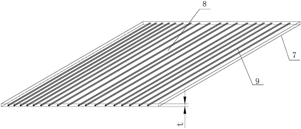
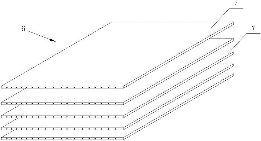
[0034] see Figures 1 to 3 , an elevator traction bearing member 6, comprising a plurality of traction bearing units 7 stacked together along the thickness direction. Each traction bearing unit 7 includes a polymer substrate 8 and a plurality of non-metallic fiber filaments 9 embedded in the polymer substrate 8 and extending continuously along the length direction of the traction bearing unit 7 . In this embodiment, the polymer substrate 8 is epoxy resin, and the non-metal fiber filament 9 is carbon fiber.

[0035] In the present embodiment, the diameter d of the non-metallic fiber wire 9 is 3 μm, and the traction bearing unit 7 is a flat belt-like structure without teeth on the surface. The thickness t of each traction bearing unit 7 is 4 μm, and the traction bearing member 6 of the elevator The section thickness T is 0.1 mm, and the section width B of the elevator traction bearing member 6 is 10-250 times of the section thickness T. According to needs, the diameter d of th...

Embodiment 2

[0038] see Figure 4 The difference between this embodiment and Embodiment 1 is that: the elevator traction bearing member 6 of this embodiment is formed by arranging a plurality of traction bearing units 7 along the width direction, wherein the thickness of each traction bearing unit 7 is 7mm, the cross-sectional thickness of the elevator traction bearing member 6 is also 4mm; the polymer substrate 8 constituting the traction bearing unit 7 is rubber, specifically TPU; the non-metal fiber filament 9 is glass fiber, and the diameter of the non-metal fiber filament 9 is d is 80 μm.

Embodiment 3

[0040] see Figure 5 The difference between this embodiment and Embodiment 1 is that the traction bearing unit 7 constituting the elevator traction bearing member 6 in this embodiment is a toothed belt-shaped structure with a plurality of teeth 71 on the lower surface, and fine concaves on the upper surface. The groove 72; the polymer substrate 8 is rubber, specifically CR; the non-metal fiber filament 9 is nylon fiber, and the diameter of the non-metal fiber filament 9 is 40 μm.


PUM


Abstract

The invention discloses an elevator traction bearing component and an elevator. The elevator traction bearing component comprises one or more traction bearing units; each traction bearing unit includes a polymer substrate, and at least one nonmetal fiber embedded in the polymer substrate and continuously extending in the length direction of the traction bearing unit; the nonmetal fibers are glass fibers, carbon fibers or nylon fibers; and diameters d of the nonmetal fibers are 3-80 microns. The nonmetal fibers are leaded into the elevator traction bearing component to realize lighter design of the elevator traction bearing component, so that the weight of the elevator traction bearing component is largely reduced, and the use noise of the elevator traction bearing component is lowered. The elevator adopting the elevator traction bearing component with lighter design can be more suitable for a compact building hoistway to improve the elevator operation comfort.

Description

technical field [0001] The invention relates to an elevator traction bearing member and an elevator used for transmitting power and lifting a car in an elevator. Background technique [0002] In the traction elevator, the relative movement of the car and the counterweight is achieved by the friction between the traction rope and the traction wheel. This force is called traction or driving force. The traction rope is one of the elevator traction load-bearing components. Most of the current elevators use steel wire ropes as the elevator traction load-bearing components. However, with the development of elevator technology, elevator traction load-bearing components are developing in the direction of light weight. Due to the disadvantages of heavy weight, large diameter and high noise, traditional steel wire ropes cannot meet the needs of elevators with limited installation space and lightweight design. need. In order to solve such problems, elevator traction load-bearing com...

Claims


Application Information

Patent Timeline
Patent Type & Authority Applications(China)
IPC IPC(8): B66B7/06
CPCB66B7/06
Inventor 陈远峰陶宪德
Owner SJEC CORP
Learn More