Cast-in-situ bored pile hole-forming device and method

A technology of bored piles and hole-forming devices, which is applied to sheet pile walls, earthwork drilling, wellbore/well components, etc., can solve the problems of inability to meet construction requirements, verticality of the pile body, and the reduction of the diameter of the pile body and the inclusion of mud. Sand and other problems, to achieve the effect of shortening the construction time of a single pile, improving the quality of the pile, and improving the quality

Active Publication Date: 2016-07-27
SHANGHAI MECHANIZED CONSTR GRP
View PDF6 Cites 14 Cited by
  • Summary
  • Abstract
  • Description
  • Claims
  • Application Information

AI Technical Summary

Problems solved by technology

Conventional positive circulation hole forming and positive circulation hole cleaning technology can no longer meet the construction requirements, especially at present, ultra-deep bored piles generally need to pass through the 7th and 9th silt layers, often due to hole quality problems Common quality problems such as the verticality of the pile body, the shrinkage of the pile body, or the inclusion of mud and sand

Method used


Image

  • Cast-in-situ bored pile hole-forming device and method
  • Cast-in-situ bored pile hole-forming device and method
  • Cast-in-situ bored pile hole-forming device and method

Examples


Embodiment Construction

[0023] The bored pile hole-forming device proposed by the present invention will be described in further detail below in conjunction with the accompanying drawings and specific embodiments. Advantages and features of the present invention will be apparent from the following description and claims. It should be noted that all the drawings are in a very simplified form and use imprecise scales, and are only used to facilitate and clearly assist the purpose of illustrating the embodiments of the present invention.

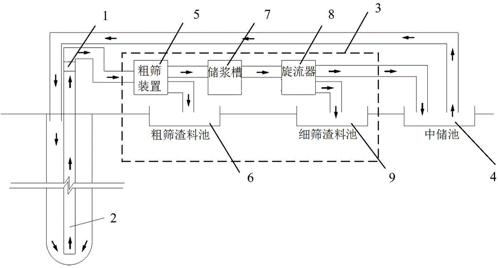
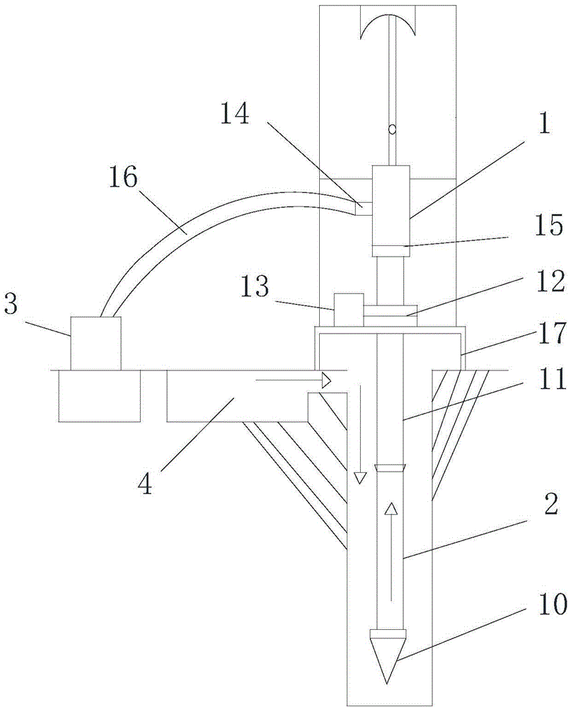
[0024] combine Figure 1 to Figure 3 , this embodiment discloses a drilling device for cast-in-situ piles, comprising: a drilling rig, a gravel pump 1, a mud purification device 3 and an intermediate storage tank 4, and the mud purification device 3 includes a coarse screening device 5, a coarse screening residue Material tank 6, slurry storage tank 7, slurry pump, cyclone 8 and fine screen slag material tank 9, the drilling rig includes a drill pipe 2, and the slurr...


PUM


Abstract

The invention discloses a cast-in-situ bored pile hole-forming device and method. Dirt slurry at the hole bottom is conveyed to a coarse screening device through a drilling rod by means of a gravel pump, a coarse slag material flows into a coarse screening slag material pool after the dirt slurry is subject to coarse screening through the coarse screening device, and the rest of the dirt slurry flows into a slurry storage tank; the slurry in the slurry storage tank is conveyed to a hydrocyclone through a slag slurry pump and is subject to fine screening through the hydrocyclone, then a fine slag material flows into a fine screening slag material pool, and the rest of the slurry flows into a middle storage tank; and the slurry inside the middle storage tank is conveyed to space between the drilling rod and the hole wall by an overflowing opening formed in the pool wall or through a slurry pump, and therefore a reverse circulation loop is formed. By adopting a pumping suction reverse circulation hole cleaning manner, the hole-forming rate and the hole cleaning efficiency can be improved, the waste slurry discharge amount is less, the single-pile construction time is shortened, the inward contraction amount of the hole wall is reduced, and the construction quality is improved. By means of two-stage screening through the coarse screening device and the hydrocyclone, the quality of slurry circulated back to holes can be improved, slag sinking to the hole bottom is further reduced effectively, and the hole wall is more stable.

Description

technical field [0001] The invention relates to the field of bored pile construction, in particular to a bored pile hole-forming device and method. Background technique [0002] With the rapid development of science and technology and economic construction, high-rise and super high-rise buildings in Shanghai are constantly rising at an unprecedented speed, and pile foundations are increasingly becoming the super-deep forms commonly used in these high-rise buildings. Due to the characteristics of no vibration, low noise and little impact on the surrounding environment of bored piles, and most of the high-rises and super high-rises in Shanghai are located in the city center, bored piles have received general attention from the Shanghai construction industry and have become the current pile foundation. One of the most popular forms of . [0003] With the continuous refresh of the building height records in Shanghai, bored piles are also constantly developing in the direction o...

Claims


Application Information

Patent Timeline
Patent Type & Authority Applications(China)
IPC IPC(8): E02D5/34E21B21/00
Inventor 沈伟城毛轶
Owner SHANGHAI MECHANIZED CONSTR GRP
Why Eureka
Try Eureka