Particle material drying and mixing equipment

A technology for mixing equipment and granular materials, which is applied in drying solid materials, dry cargo handling, non-progressive dryers, etc. It can solve the problems of product quality impact and insufficient drying of materials, and achieve the effect of increasing temperature and accelerating drying process.

Active Publication Date: 2016-07-27
山东艾克赛尔机械制造有限公司
View PDF7 Cites 9 Cited by
  • Summary
  • Abstract
  • Description
  • Claims
  • Application Information

AI Technical Summary

Problems solved by technology

The existing drying device is mainly a vertical structure, the material is added from the top, and then output after internal heating and drying. During the operation, if there is agglomeration between the materials, the drying of the materials is insufficient, which makes the product quality suffer. influences

Method used


Image

  • Particle material drying and mixing equipment
  • Particle material drying and mixing equipment

Examples


Embodiment 1

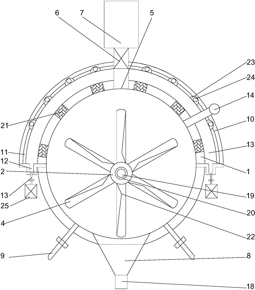
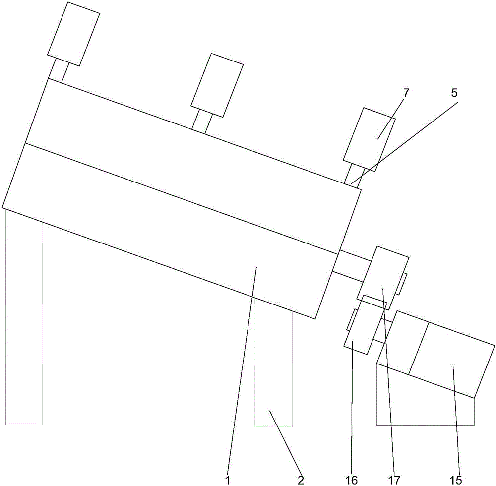
[0022] like figure 1 As shown, 1. A granular material drying and mixing equipment, comprising a hollow cylindrical drying bin and a bracket 2 arranged below the drying bin, a rotating shaft 3 is arranged inside the drying bin, and the The axis of the rotating shaft and the axis of the drying bin form an eccentric structure, and at least four blades 4 are arranged on the rotating shaft. During the rotation of the blades, the outer edges of the blades can be attached to the On the inner wall of the lower end of the drying bin, the upper end of the drying bin is provided with a feeding port 5, and the feeding port is at least 2 arranged at equal intervals along the length direction of the outer wall of the drying bin. The inside of the feed inlet is provided with a star valve 6, a vibrating feeder 7 is arranged on the feed inlet, and a discharge port 8 is arranged below the drying bin. A discharge valve 18 is arranged on the top, an air inlet is arranged on the side of the disch...

Embodiment 2

[0025] This embodiment is based on Embodiment 1, in order to speed up the drying speed, in this embodiment, preferably, a cavity 20 is provided in the middle of the rotating shaft, and an electric heater 19 is provided in the cavity. The rotating shaft is heated by an electric heater, so that the particulate matter can exchange heat during contact with the rotating shaft, and at the same time help to increase the internal temperature of the drying cylinder and accelerate the drying process.

[0026] In this embodiment, in order to avoid easy wear of a single blade due to uneven material distribution between adjacent blades, preferably, through holes are provided on the blades. The drying efficiency can be improved by making the material flow between the adjacent blades through the through holes.

[0027] In order to make the materials move relative to each other when the blades are in contact with each other, and accelerate the sufficient mixing and collision between the mater...


PUM


Abstract

The invention discloses particle material drying and mixing equipment. The equipment comprises a hollow cylindrical drying bin, and a bracket arranged below the drying bin; a rotating shaft is arranged on the inner side of the drying bin; the axis of the rotating shaft and the axis of the drying bin form an eccentric structure; at least four blades are arranged on the rotating shaft; in the rotating process of the blades, the outer side edges of the blades can be bonded on the inner wall of the lower end of the drying bin; and a feed port is formed in the upper end of the drying bin. As the rotating shaft and the drying bin are eccentrically arranged, in the rotating process of the blades, materials at the bottom of the drying bin can be totally driven to one side of an isolation cover at the upper part when passing through the bottom of the drying bin, and water in particle materials with water is output by a water collecting tank in the isolation cover in a concentrated manner; and the equipment is simple in structure and more uniform in drying of the materials.

Description

technical field [0001] The invention relates to a dry mixing equipment for granular materials. Background technique [0002] For the processing of granular objects such as desiccant and animal feed, in order to prolong their storage time, they need to be dried to reduce their water content. The existing drying device is mainly a vertical structure, the material is added from the top, and then output after internal heating and drying. During the operation, if there is agglomeration between the materials, the drying of the materials is insufficient, which makes the product quality suffer. influences. Contents of the invention [0003] The purpose of the present invention is to provide a kind of equipment for drying and mixing granular materials, which can improve the problems existing in the prior art. By adopting the eccentric setting of the rotating shaft and the drying chamber, the blade can completely turn the drying chamber when passing through the bottom of the drying...

Claims


Application Information

Patent Timeline
IPC IPC(8): F26B11/14F26B25/00F26B25/02F26B25/04
CPCF26B11/14F26B25/002F26B25/02F26B25/04
Inventor 吕爱萍
Owner 山东艾克赛尔机械制造有限公司
Why Eureka
Try Eureka